Device for lifting articles bound together by a strapping device

A technology for bundling devices and articles, which is applied to the device field of articles, can solve problems such as the structural complexity of hooking cranes, and achieve the effect of simplifying the lifting device

Active Publication Date: 2018-06-15
STEVENEL
View PDF9 Cites 0 Cited by
  • Summary
  • Abstract
  • Description
  • Claims
  • Application Information

AI Technical Summary

Problems solved by technology

[0003] The disadvantage of the above solution is the complexity of the structure of the hook crane, since each hook crane has elastic fasteners for grabbing the member and its accessories

Method used


Image

  • Device for lifting articles bound together by a strapping device
  • Device for lifting articles bound together by a strapping device
  • Device for lifting articles bound together by a strapping device

Examples


Embodiment Construction

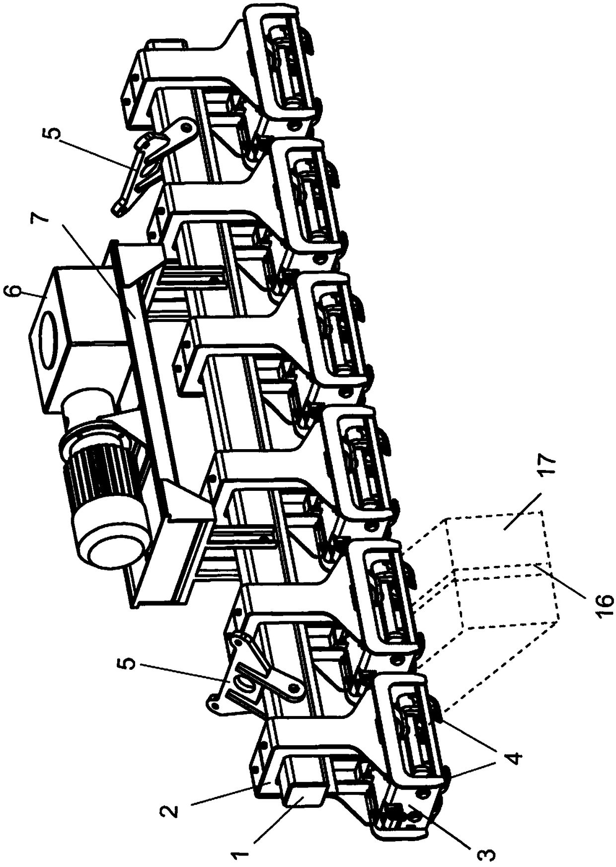
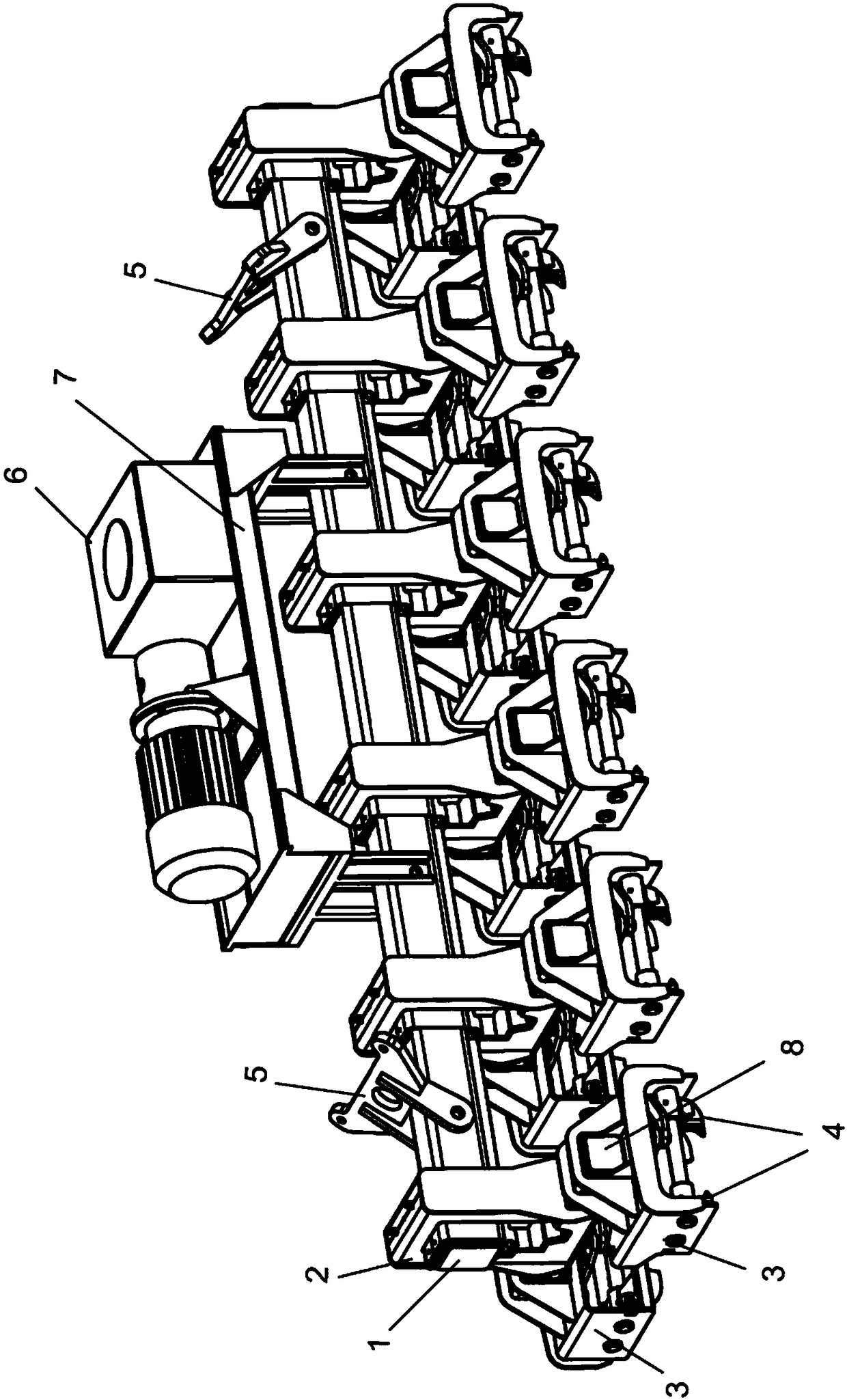
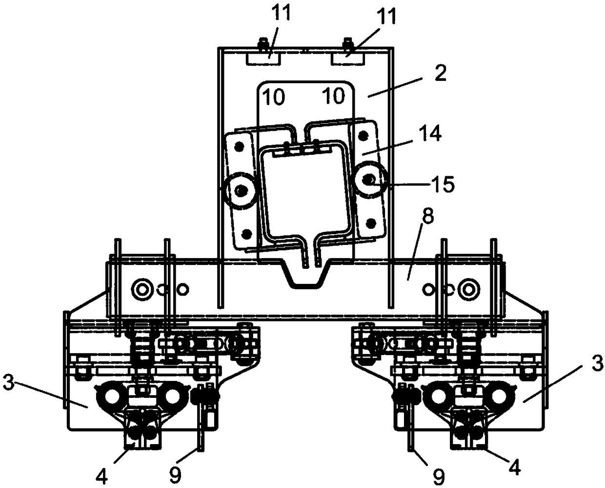
[0015] figure 1 Shown are hook trolleys 3 placed on the horizontal beam 1 of the lifting device, each hook trolley each comprising two gripping member pairs 4 at a distance from each other. This distance may even be as small as 30% of the width of the raised pulp unit 17, ie as small as 30% of the length of the sling / wire 16 on the top surface portion of the pulp unit. This makes it possible to provide a narrower and at the same time lighter hitch crane 3 . The hook crane 3 is suspended on the horizontal beam 1 by the groove member 2, and the horizontal beam 1 can move in the vertical direction in the groove gap and can also tilt therein. The hitch trolley 3 can be moved along the horizontal beam 1 in a manner known per se by means of moving means, such as hydraulic cylinders or electric drives, arranged on the bottom surface of the horizontal beam 1 . The gripping member 4 is also moved by means of moving means such as hydraulic cylinders or electric drives. figure 1 The s...


PUM


Abstract

A lifting device for lifting articles such as pulp units bound together by tying means, the device comprising at least one horizontal beam (1) connected to a crane and having attached thereto a plurality of The hook cranes (3) moving on the beam, when the grabbing members (4) belonging to the cranes are brought close to each other, each hook crane (3) located at the item to be lifted is arranged as a strapping device for grabbing the item, binding The device is thus suspended from the gripping member. The hook crane (3) is provided with a pair or two pairs of grasping members with a fixed distance from each other, and its grasping movement is parallel movement, and each hook crane (3) is suspended at an adjustable distance from each other by the following components: The trough member (2) of the horizontal beam (1), the trough member (2) allows each hook crane (3) to move a predetermined distance respectively in the vertical direction and tilt to a predetermined angle in the trough member; intermediate beams (8) of the beams (1), each intermediate beam (8) attached to be suspended from the horizontal beam (1) by channel members (2), the intermediate beams (8) transverse to the horizontal beams (1) and the channel members (2) Each hook crane (3) or pair of hook cranes is allowed to move a predetermined distance in the vertical direction and tilt to a predetermined angle in the trough member, respectively.

Description

technical field [0001] The present invention relates to a device for lifting articles such as pulp units bound together by a lashing device, the device comprising at least one horizontal beam attached to a crane and having a plurality of hooks attached thereto The crane is also movable along this beam, each hook crane located at the item to be lifted is provided as a strapping device for grabbing the item when the grabbing members belonging to the crane are brought close to each other, the strapping device is thus suspended on the grabbing on the component. Background technique [0002] When lifting a load by means of slings, while the lifting device is being brought over the load, the slings are either already around the load, or they slip under the load, and then the straps are also placed in the hooks of the lifting device. Currently, the aim is to grab the slings by means of hook cranes belonging to the lifting device, so that manpower is no longer required to fasten or...

Claims


Application Information

Patent Timeline
Patent Type & Authority Patents(China)
IPC IPC(8): B66C1/28
CPCB66C1/28B66C13/20
Inventor 海基·海萨罗
Owner STEVENEL
Why Eureka
Try Eureka