Solid-state detector and method for resetting residue charges by illumination in the case of a solid-state detector

a solid-state detector and residue charge technology, applied in the field of solid-state detectors, can solve the problems of non-uniform reset distribution and inability to read all the charge contained, and achieve the effect of uniform image quality of digital x-ray records

Active Publication Date: 2010-08-03
SIEMENS HEALTHCARE GMBH
View PDF7 Cites 1 Cited by
  • Summary
  • Abstract
  • Description
  • Claims
  • Application Information

AI Technical Summary

Benefits of technology

[0009]In at least one embodiment of the present invention, uniform image quality of digital X-ray records is achieved with a solid-state detector, even when individual light-emitting diodes are faulty.
[0010]In the solid-state detector according to at least one embodiment of the invention and the method according to at least one embodiment of the invention, the capability to drive and control the intensity of the light-emitting diodes individually allows the reset light source to be easily and effectively matched to different requirements and applications. It is thus possible to match the power of different light-emitting diodes to one another, or to substitute other light-emitting diodes for failed light-emitting diodes by intensity adaptation, so that it is possible to ensure that the digital X-ray records have a uniform image quality, without artifacts.
[0011]According to at least one embodiment of the invention, in the event of a failure or a malfunction of at least one light-emitting diode, the intensities of the serviceable light-emitting diodes are driven and controlled such that the intensity and / or the homogeneity of the reset light source remain / remains constant. A constant intensity ensures effective and error-free reduction of ghosting artifacts, and thus the image quality of the X-ray records is particularly good. A constant homogeneity of the reset light source ensures that switching artifacts are reduced or minimized, and thus likewise ensures that the image quality of the X-ray records is particularly good.
[0012]The light-emitting diodes advantageously have at least two intensity levels, and can be switched from a first intensity level to a second intensity level, and back. The different intensity levels and their control allow improved matching of the resetting process by the reset light source: if the resetting process is not adequate in the event of a low intensity level, then the intensity of the light-emitting diodes can be increased, while on the other hand their intensity can be reduced in order to save energy. Even better reset matching can be ensured by the intensity of the light-emitting diodes advantageously being continuously variable. This can be achieved, for example, by way of a potentiometer control.
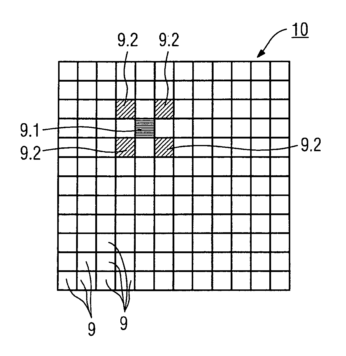
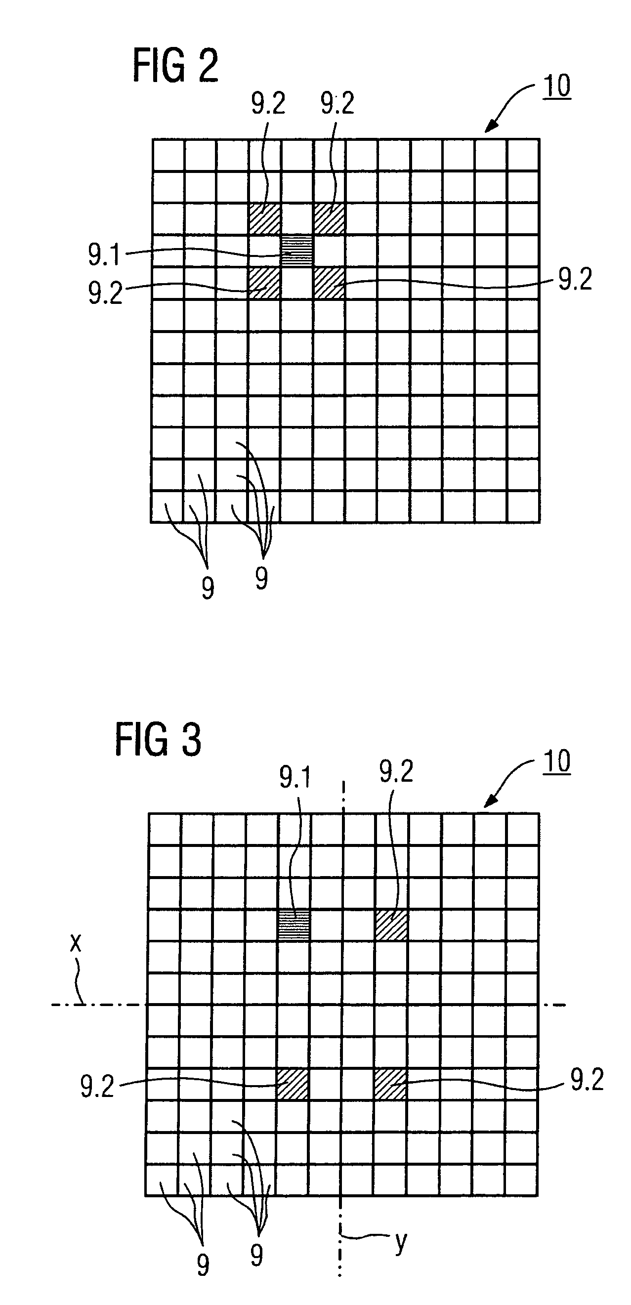
[0014]The intensities of at least some of the light-emitting diodes which are arranged adjacent to a failed or malfunctioning light-emitting diode are advantageously increased. This makes it possible to compensate for failed light-emitting diodes and, overall, prevents the image quality from being adversely affected by malfunctioning or failed light-emitting diodes. In order to compensate for the inhomogeneity of the reset light source which is caused by a malfunctioning or failed light-emitting diode, light-emitting diodes which are arranged symmetrically with respect to a failed light-emitting diode with respect to at least one axis of symmetry (x; y) of the active matrix (5) are switched off.

Problems solved by technology

The electrical charge is held in a comparatively stable manner in these traps because the energy level is particularly low, so that it is not possible to read all of the charge contained in the trap during the reading process which follows image recording.
However, if any individual light-emitting diodes fail, then, in some cases, this can result in a non-uniform reset distribution, which is then reflected in the digital X-ray record.

Method used


Image

  • Solid-state detector and method for resetting residue charges by illumination in the case of a solid-state detector
  • Solid-state detector and method for resetting residue charges by illumination in the case of a solid-state detector
  • Solid-state detector and method for resetting residue charges by illumination in the case of a solid-state detector

Examples


Embodiment Construction

[0020]The terminology used herein is for the purpose of describing particular embodiments only and is not intended to be limiting of the present invention. As used herein, the singular forms “a”, “an” and “the” are intended to include the plural forms as well, unless the context clearly indicates otherwise. It will be further understood that the terms “includes” and / or “including”, when used in this specification, specify the presence of stated features, integers, steps, operations, elements, and / or components, but do not preclude the presence or addition of one or more other features, integers, steps, operations, elements, components, and / or groups thereof.

[0021]In describing example embodiments illustrated in the drawings, specific terminology is employed for the sake of clarity. However, the disclosure of this patent specification is not intended to be limited to the specific terminology so selected and it is to be understood that each specific element includes all technical equi...


PUM


Abstract

For a uniform image quality of digital X-ray records, a solid-state detector is provided. The detector includes light-sensitive pixel elements arranged in an active matrix, and a reset light source arranged behind them in the radiation direction of X-ray radiation, with the reset light source being in the form of an arrangement with light-emitting diodes and with the light-emitting diodes being designed such that can be driven individually and their intensity can be controlled individually. At least one of a failed and malfunctioning light-emitting diode is detectable. The intensities of the serviceable light-emitting diodes are driven and controlled in the event of a failure or a malfunction of at least one light-emitting diode in such a manner that the intensity and / or the homogeneity of the reset light source remains the same.

Description

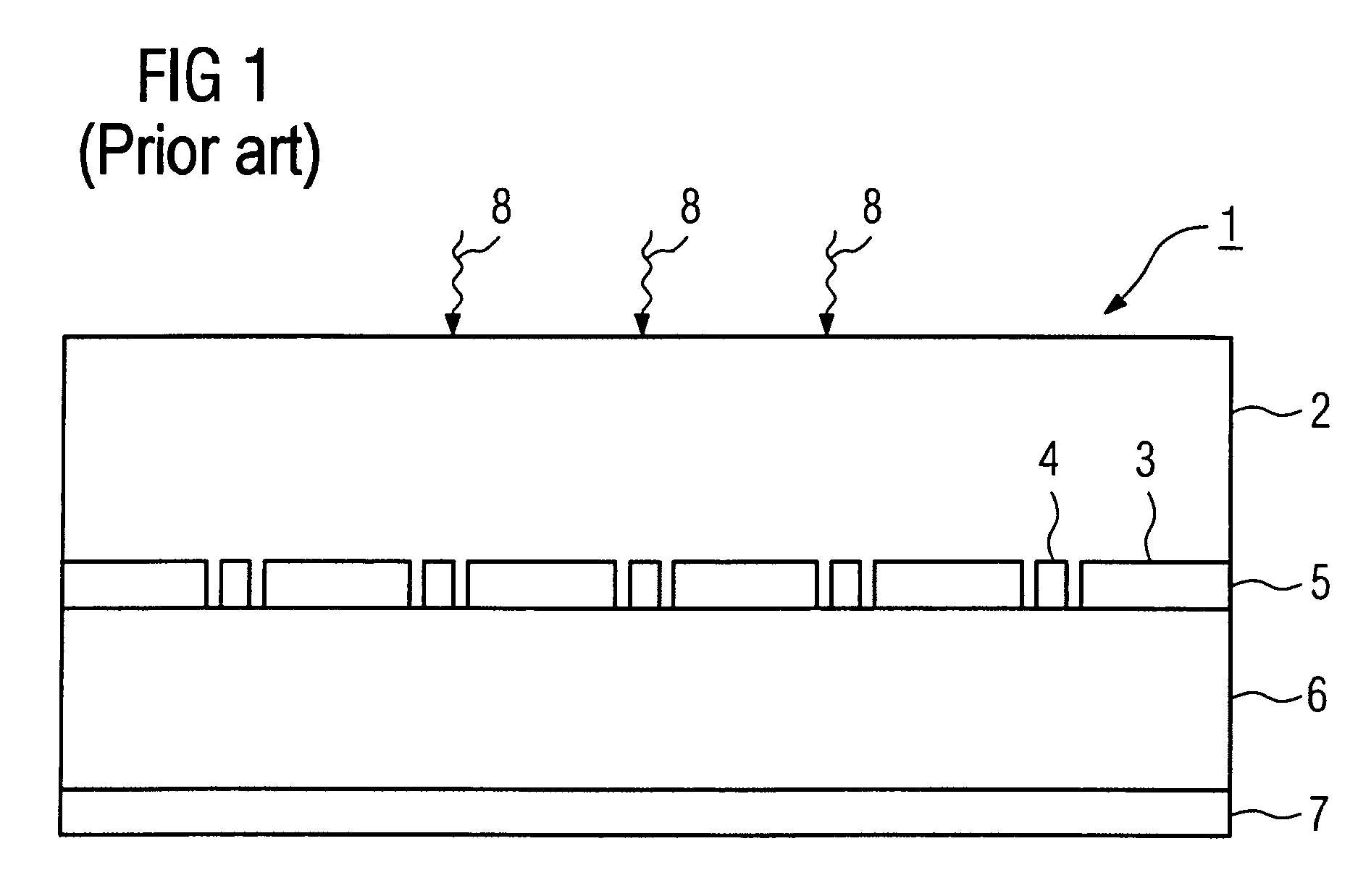
PRIORITY STATEMENT[0001]The present application hereby claims priority under 35 U.S.C. §119 on German patent application number DE 10 2005 037 898.6 filed Aug. 10, 2005, the entire contents of which is hereby incorporated herein by reference.FIELD[0002]The invention generally relates to a solid-state detector. For example, it may relate to one including light-sensitive pixel elements which are arranged in an active matrix, and including a reset light source which is arranged behind them in the radiation direction of X-ray radiation, and / or to a method for resetting residual charges by illumination.BACKGROUND[0003]Solid-state detectors based on active reading matrices, for example composed of amorphous silicon (a-Si) with a scintillator layer coating in front of it have been known for many years. The incident X-ray radiation is converted to visible light in the scintillator layer, is converted to an electrical charge in light-sensitive pixel elements in the reading matrix, and is sto...

Claims


Application Information

Patent Timeline
Patent Type & Authority Patents(United States)
IPC IPC(8): H05G1/64
CPCG01T1/24H01L27/14658H01L27/14609H04N5/32
Inventor HORNIG, MATHIAS
Owner SIEMENS HEALTHCARE GMBH
Why Eureka
Try Eureka