Arrangement for improving the image field in ophthalmological appliances

a technology for ophthalmological appliances and ophthalmology, which is applied in the field of ophthalmological appliance arrangement for improving the image field, can solve the problems of difficult to achieve the variable, difficult to achieve the exact slit width, and small slit width, so as to achieve the effect of improving the image field and high image quality

Inactive Publication Date: 2006-08-03
CARL ZEISS MEDITEC AG
View PDF11 Cites 14 Cited by
  • Summary
  • Abstract
  • Description
  • Claims
  • Application Information

AI Technical Summary

Benefits of technology

[0014] It is the primary object of the present invention to improve the image fields of the known illumination components and irradiation components of ophthalmic diagnostic instruments and therapeutic instruments in such a way that structures, images and characters projected in or on the eye have a uniformly high image quality over extensive areas of the eye.
[0017] With the present solution, a uniform image quality can be achieved over extensive areas of the eye. Accordingly, more comprehensive information can be acquired more quickly through appropriate evaluating algorithms. In particular, the solution can be applied for determining biometric data of an eye, wherein curved areas of the eye are illuminated over a large area with a very fine structure.

Problems solved by technology

It is difficult to achieve the variable, very small slit widths that are required for high optical detail resolution within the optical section.
Further, the alignment of the mechanical subassemblies is very complicated and is made even more difficult by the thermal expansion of the subassemblies.
It is almost impossible to reproduce exact slit widths.
A section bundle that is focused over the entire extent of the human eye cannot be achieved by the previously known solutions.
In this solution, it is disadvantageous that the irradiation can generally only be carried out successively point by point so that the treatment process is time-consuming.
These solutions are disadvantageous in that the variability of the light field geometries is limited.
Further, the system for receiving the scattered light from the eye has a physically limited depth of field which cannot fully acquire the area over which the sharp laser section image extends.
In current ophthalmic instruments, the straight or even oppositely curved image planes of the illumination components and irradiation components have a disadvantageous effect.
Accordingly, evaluation of the distortion of the structures is made harder or is only possible within a limited area.

Method used


Image

  • Arrangement for improving the image field in ophthalmological appliances
  • Arrangement for improving the image field in ophthalmological appliances

Examples


Embodiment Construction

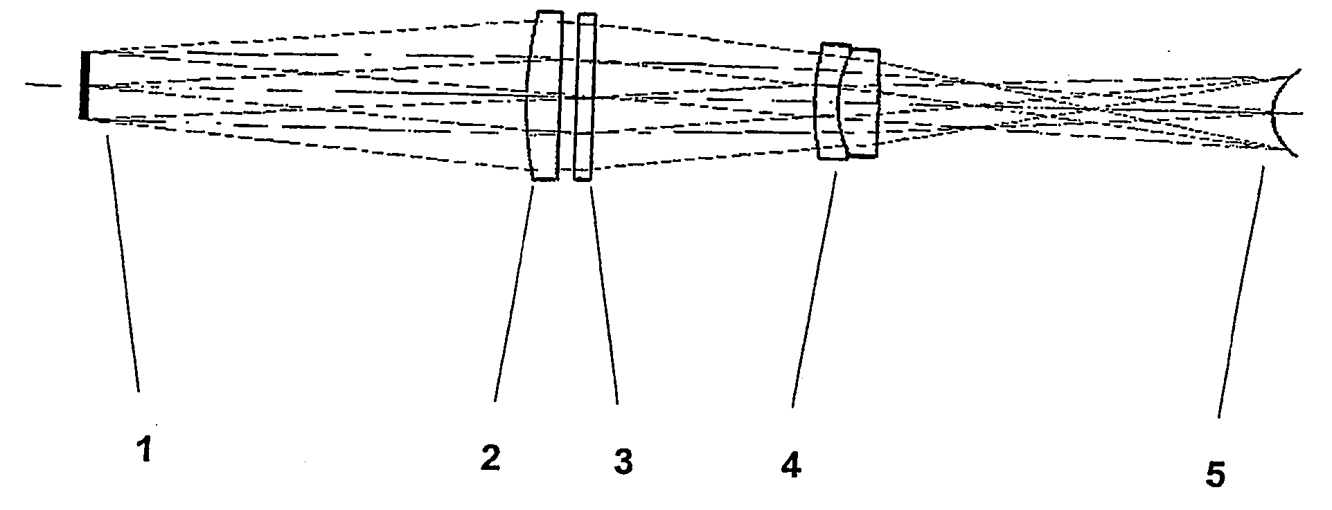
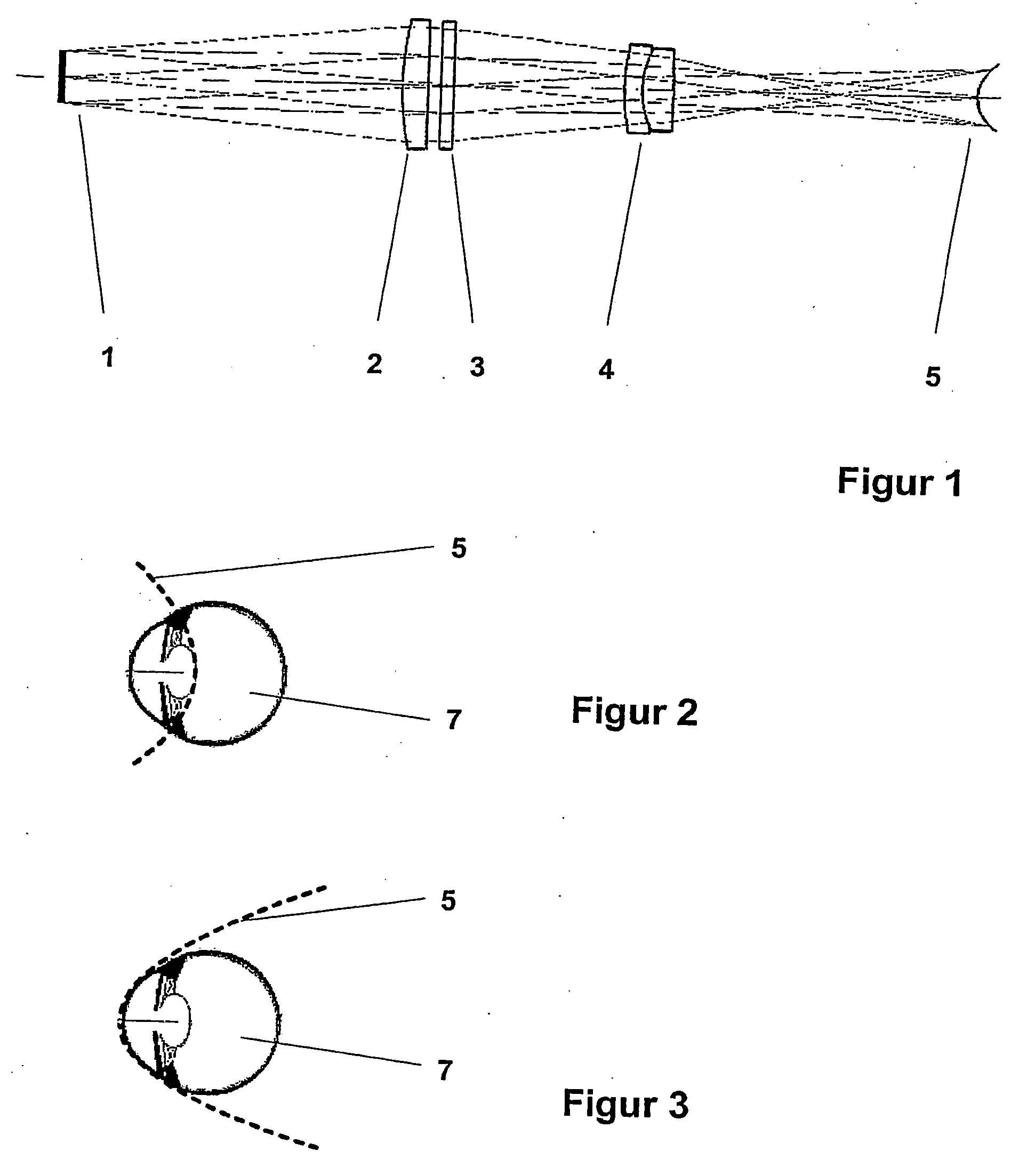
[0022] In the arrangement for improving the image field in ophthalmic instruments, a diffractive optical element (DOE) 3 is arranged in the illumination beam path of the irradiation unit in order to achieve a specific shape of the image plane 5. The diffractive optical element 3 can be located on the surface of another optical element or, as is shown in FIG. 1, can be arranged in the beam path as a separate element. The type of light source used and the type of beam shaping, i.e., structure generation or pattern generation, are not relevant (not shown). Therefore, FIG. 1 shows the beam path proceeding from the respective illumination pattern 1. Proceeding from the illumination pattern 1, the illumination beams travel to the DOE 3 through optics 2 serving as a first imaging system. The shape of the illumination beams is changed by the DOE 3 in such a way that an image plane 5 adapted to the curvature of the respective element to be irradiated results in the eye 7 to be irradiated. FI...


PUM


Abstract

The present invention is directed to an arrangement by which the image field of the illumination components and irradiation components of ophthalmic instruments for diagnosis and therapy is improved. In the arrangement according to the invention, one or more diffractive optical elements is / are arranged additionally in the illumination beam path for deliberate shaping of the image plane in the eye to be irradiated. These diffractive optical elements can be located on the surface of other optical elements, swiveled into the illumination beam path, and their wavelength changed by filters. The image plane can be adapted to the spherical contour of the eye so that the projected characters and structures have a uniformly high image quality in the center and in the edge area of the eye. The present invention is applicable for variable illumination for diagnosis and treatment of the eye, in particular for irradiation of the eye lens and other parts of the eye such as the cornea or retina. The arrangement can be used in a great variety of ophthalmic instruments such as fundus cameras, slit lamps, laser scanners, OPMI instruments or surgical microscopes.

Description

CROSS-REFERENCE TO RELATED APPLICATIONS [0001] This application claims priority of International Application No. PCT / EP2003 / 014689, filed Dec. 20, 2003 and German Application No. 103 07 741.3, filed Feb. 24, 2003, the complete disclosures of which are hereby incorporated by reference.BACKGROUND OF THE INVENTION [0002] a) Field of the Invention [0003] The present invention is directed to an arrangement by means of which the image field of the illumination components and irradiation components of ophthalmic instruments for diagnosis and therapy is improved. The arrangement is suitable in particular for ophthalmic instruments in which it is important to achieve a uniformly high image quality over broad regions of the eye. [0004] b) Description of the Related Art [0005] This is the case, for example, in slit lamps. A light section is generated in the interior of the eye being examined by means of slit image projection. To ensure an exact evaluation of the section images generated in thi...

Claims


Application Information

Patent Timeline
Patent Type & Authority Applications(United States)
IPC IPC(8): A61B3/10A61B3/00A61B3/135A61F9/01
CPCA61B3/00A61B3/135A61F9/008A61F2009/00846A61F2009/00863A61F2009/0087A61F2009/00872
Inventor KOSCHMIEDER, INGODOBSCHAL, HANS-JUERGEN
Owner CARL ZEISS MEDITEC AG
Why Eureka
Try Eureka