
Arrangement for radiation of a radio-frequency field

a radiofrequency field and radio frequency field technology, applied in the direction of instruments, diagnostic recording/measuring, and using reradiation, can solve the problems of particular disruptive fluctuations, unwanted fluctuations, etc., and achieve the effect of improving the passive compensation of inhomogeneities of the b1 field

Inactive Publication Date: 2010-02-16
SIEMENS HEALTHCARE GMBH
View PDF7 Cites 1 Cited by
  • Summary
  • Abstract
  • Description
  • Claims
  • Application Information

AI Technical Summary

Benefits of technology

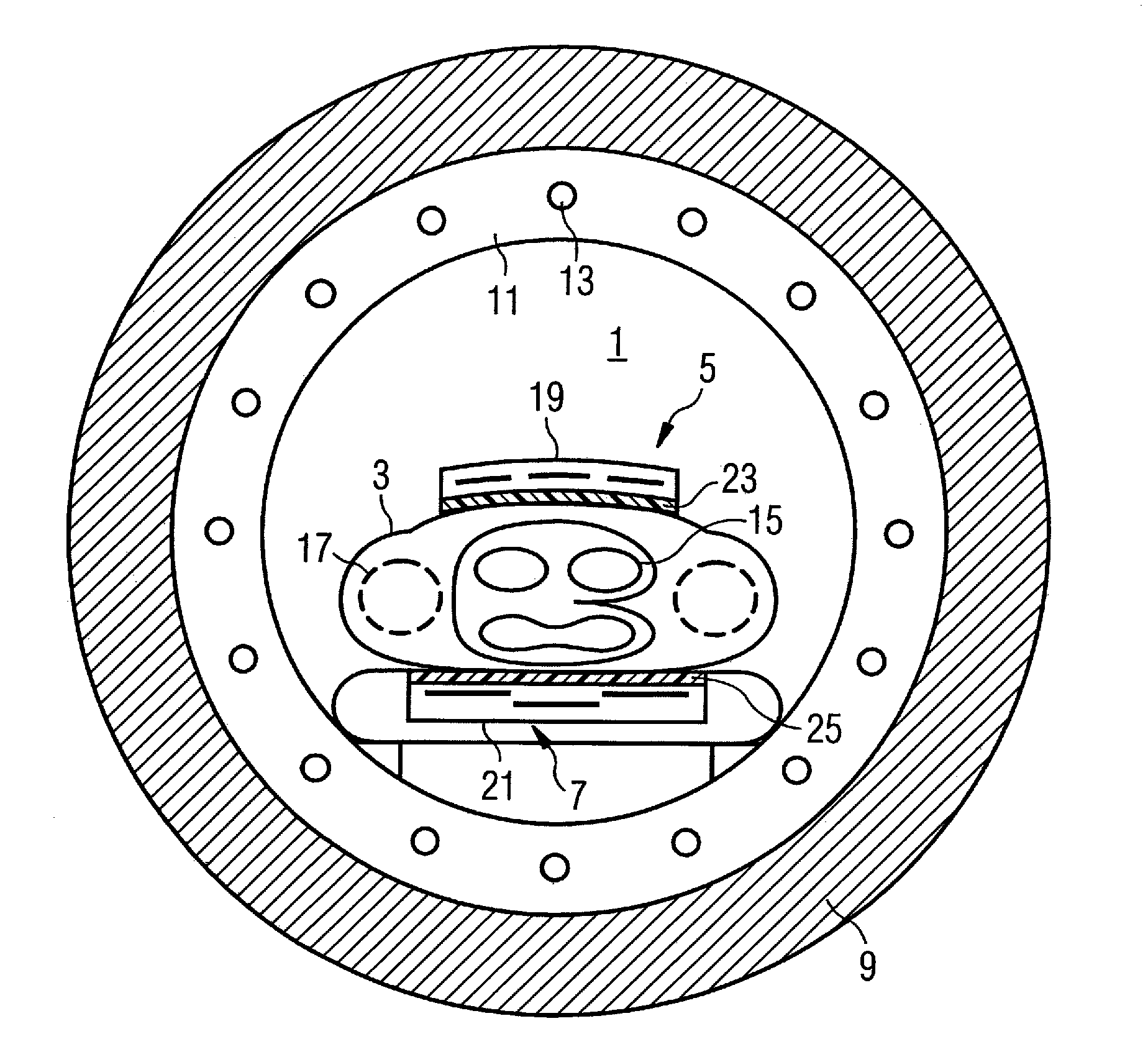
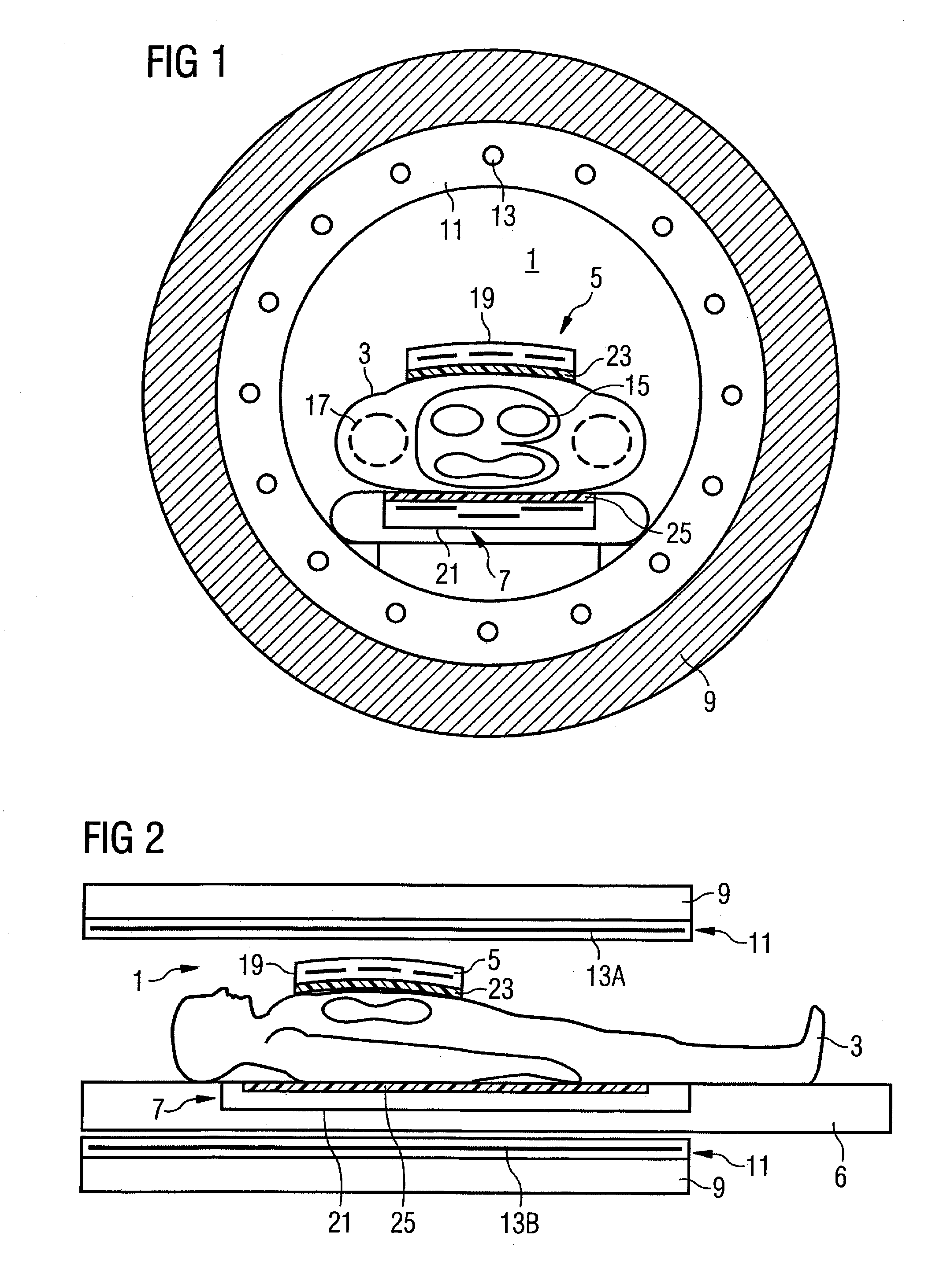
The present invention provides an improved arrangement for compensating inhomogeneities of a B1 field in a radio-frequency field radiation examination subject. The arrangement includes a local coil unit with a housing and insulating dielectric material at least one part of which compensates for B1 field inhomogeneities. The insulating dielectric material can be fixed but detachable from the housing, allowing for flexible adjustment of compensation. The arrangement enables optimal compensation based on the requirements of the measurement result, user-specific focusing in the image representation, and fine-stepped adaptation to the examination conditions. The insulating dielectric material exhibits a relative permittivity of greater than 50 and a dielectric loss factor of tan δ smaller than 2.5×10⁻², and is preferably an optimally closed area of 100 cm2 to 500 cm2 in size.

Problems solved by technology

These unwanted fluctuations in particular disruptively occur at magnetic flux densities of more than 1.5 Tesla.

Method used


Image

  • Arrangement for radiation of a radio-frequency field
  • Arrangement for radiation of a radio-frequency field
  • Arrangement for radiation of a radio-frequency field

Examples


first embodiment

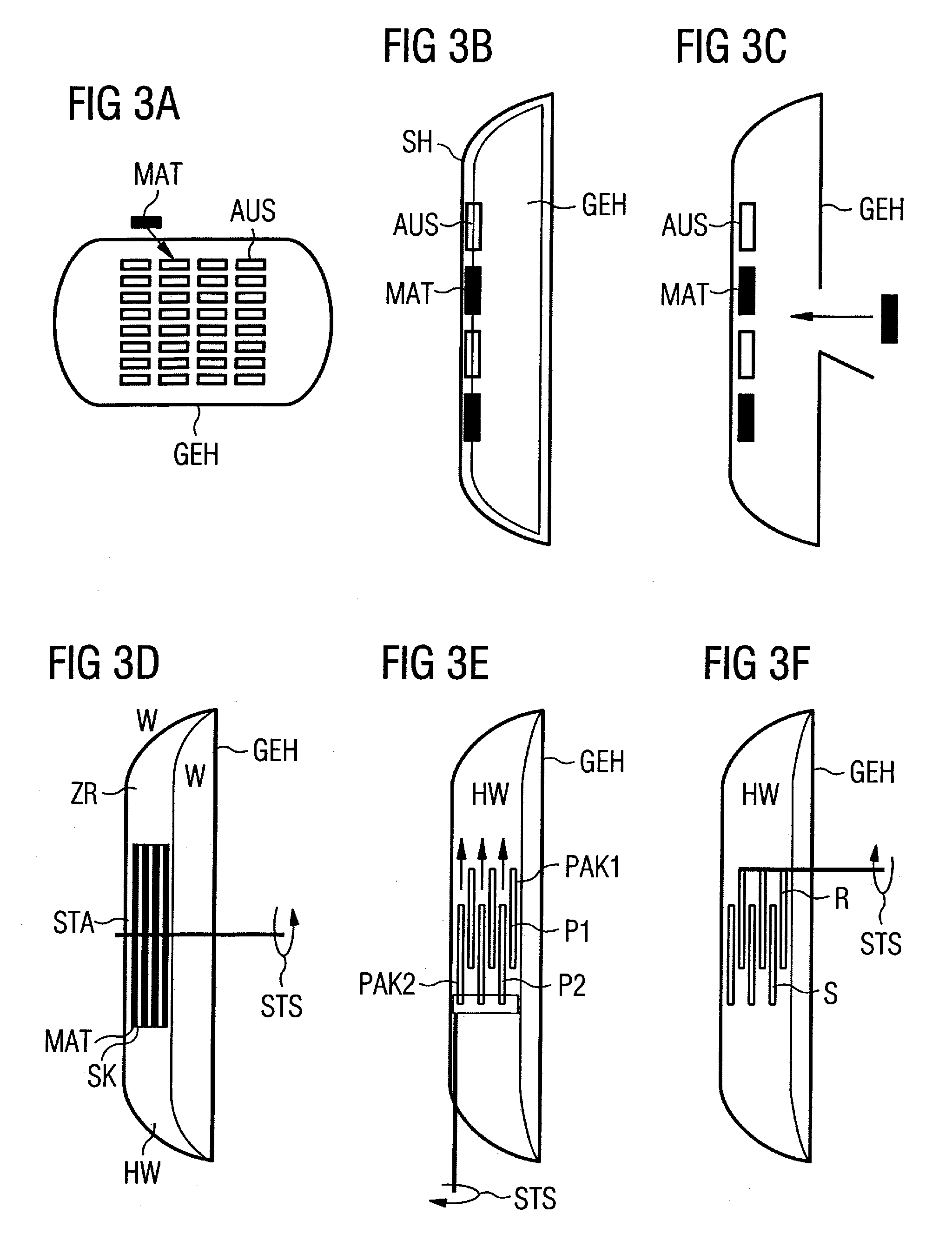
[0046]In a first embodiment according to FIG. 3A, recesses AUS for pre-assembled material shapes are provided at the housing GEH in order to adjust the total effect of the material MAT specific to the customer. The material MAT can be fashioned in the form of a pin or, a bar, for example.

[0047]The housing GEH itself is advantageously produced from an electrically neutral to weakly “dielectrically conductive” material.

[0048]The recesses AUS for material acceptance are, for example, distributed on the housing GEH like a checkerboard so that the user can occupy the recesses AUS at arbitrary points with the insulating dielectric material MAT.

[0049]If the occupation of the recesses ensues at an outer housing side, means for locking or for securing the material in the recess are provided (not shown here). A demounting of the local coil is therewith advantageously prevented; the occupation ensues from the outside without having to open the housing GEH.

second embodiment

[0050]In a second embodiment according to FIG. 3B the housing GEH and the respectively arranged material MAT are surrounded by a protective casing SH. This protective casing SH is closely conformed to the housing GEH in order to avoid a sliding of the material MAT used for compensation out from the associated positions.

[0051]This variant offers a maximum flexibility and allows an “application-specific” compensation given recurring examinations.

[0052]The user designs the properties and / or the distribution of the compensation material, adapted to the specific application. The optimization of the homogeneity of the B1 field is implemented iteratively and interactively.

third embodiment

[0053]In a third embodiment according to FIG. 3C, the housing GEH is designed for opening. An adaptation of the compensation material MAT inside the housing GEH is implemented at the factory or by an authorized laboratory. The pre-occupation again ensues according to customer-specific specifications.


PUM


Abstract

An arrangement for radiation of a radio-frequency field into an examination subject has a local coil unit with a housing. An insulating dielectric material is embodied at least at one part of the housing in order to passively compensate an inhomogeneity of the B1 field that occurs in the examination subject. An adjustment arrangement allows for fixed but detachable provision of the insulating dielectric material at the housing part.

Description

BACKGROUND OF THE INVENTION[0001]1. Field of the Invention[0002]The invention concerns an arrangement for radiation of a radio-frequency field into an examination subject in a magnetic resonance apparatus.[0003]2. Description of the Prior Art[0004]In magnetic resonance tomography, an examination subject is exposed to an optimally homogeneous, static basic magnetic field. This basic magnetic field is generated by a basic field magnet of the magnetic resonance apparatus.[0005]Rapidly switched gradient fields for spatial coding of the magnetic resonance signals are superimposed on the basic magnetic field during the acquisition of the magnetic resonance images. The gradient fields are generated by gradient coils.[0006]Radio-frequency pulses of a defined field strength are radiated into the examination subject with radio-frequency antennas. The magnetic flux density of these radio-frequency pulses is typically designated with B1; the pulse-shaped radio-frequency field is called the B1 f...

Claims


Application Information

Patent Timeline
Patent Type & Authority Patents(United States)
IPC IPC(8): G01V3/00
CPCG01R33/341G01R33/3415G01R33/5659
Inventor LAZAR, RAZVANRENZ, WOLFGANGSPECKNER, THORSTEN
Owner SIEMENS HEALTHCARE GMBH
Learn More