
Method for adjustment of a shim device of a magnetic resonance apparatus

Inactive Publication Date: 2008-04-17
SIEMENS HEALTHCARE GMBH
View PDF4 Cites 5 Cited by
  • Summary
  • Abstract
  • Description
  • Claims
  • Application Information

AI Technical Summary

Benefits of technology

[0011] An object of the invention is to provide a method with which an optimal shim data set can be determined and applied in a faster and more reliable manner.
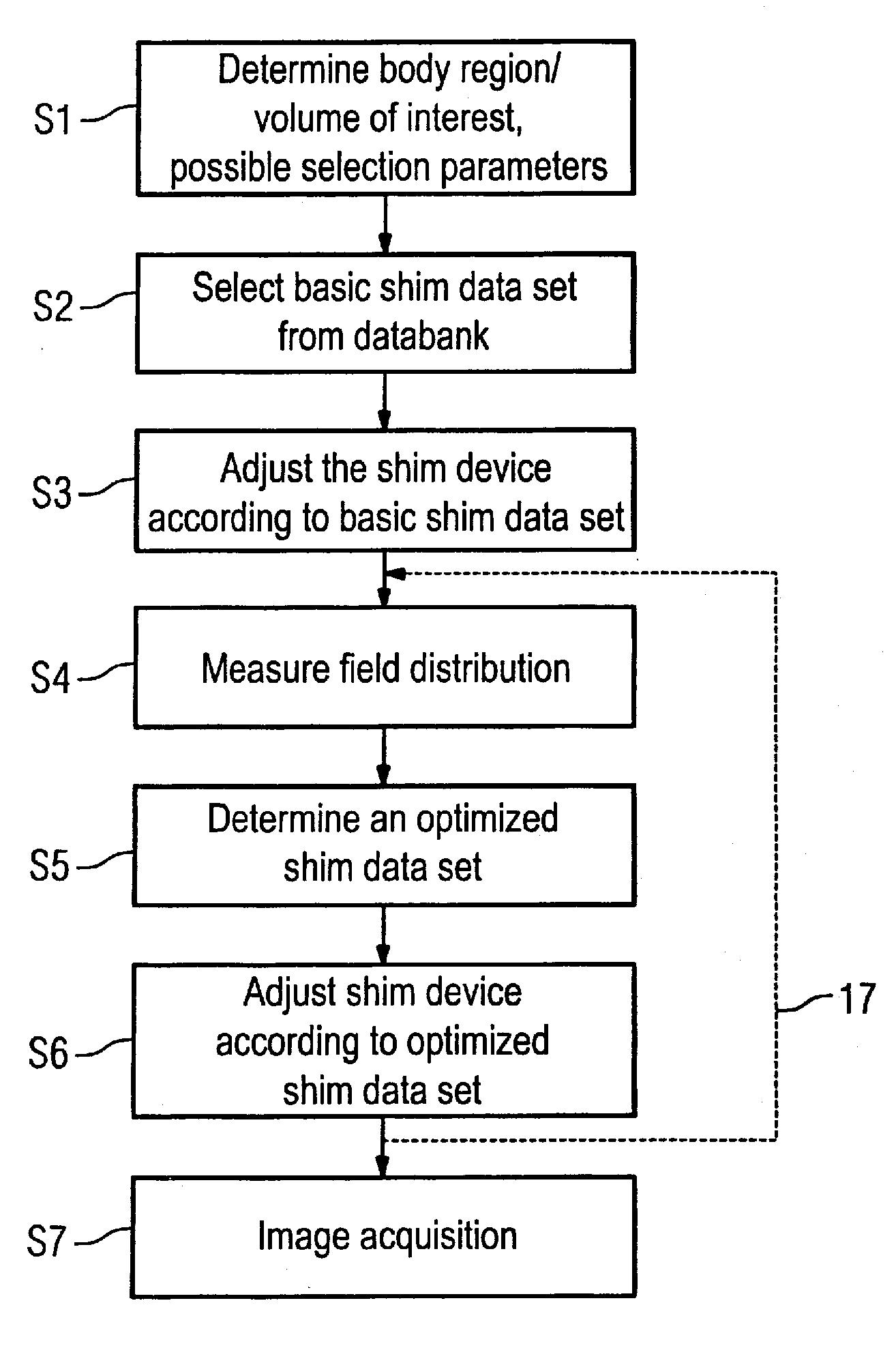
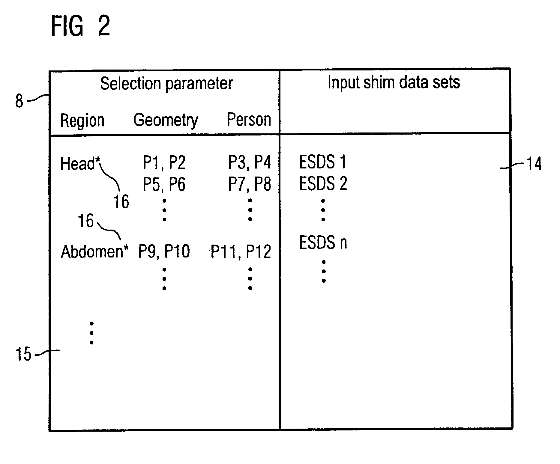
[0013] The primary problem of the conventional method lies in that the basic shim data set is based on the measurements mode during the installation of the magnetic resonance apparatus. Introduction of a body into the patient acceptance opening of the apparatus leads in part to greater inhomogeneities, such that the algorithm for optimization selects a poor starting point and does not always satisfactorily converge, or may even diverge. The inventive method provides a number of input shim data sets, organized according to various body regions, that are stored in a databank. Depending on the body region in which the image acquisition should ensue, one of the input shim data sets is then selected as a basic data set that then offers an improved starting point for the following determination of the optimized shim data set. Since the selected basic shim data set already lies much closer to the optimal shim data set to be determined, a better and faster convergence as well as a lower tendency toward error is achieved.
[0018] It is also possible for further selection parameters to be considered in the selection of the basic shim data set. The input shim data sets are then differentiated not only specific to the body region but also for further selection parameters, such that a selection of an even more suitable basic shim data set can ensue by adherence to these further criteria. The convergence is thereby further increased and the tendency toward error is further reduced.

Problems solved by technology

The primary problem of the conventional method lies in that the basic shim data set is based on the measurements mode during the installation of the magnetic resonance apparatus.
Introduction of a body into the patient acceptance opening of the apparatus leads in part to greater inhomogeneities, such that the algorithm for optimization selects a poor starting point and does not always satisfactorily converge, or may even diverge.

Method used


Image

  • Method for adjustment of a shim device of a magnetic resonance apparatus
  • Method for adjustment of a shim device of a magnetic resonance apparatus
  • Method for adjustment of a shim device of a magnetic resonance apparatus

Examples


Embodiment Construction

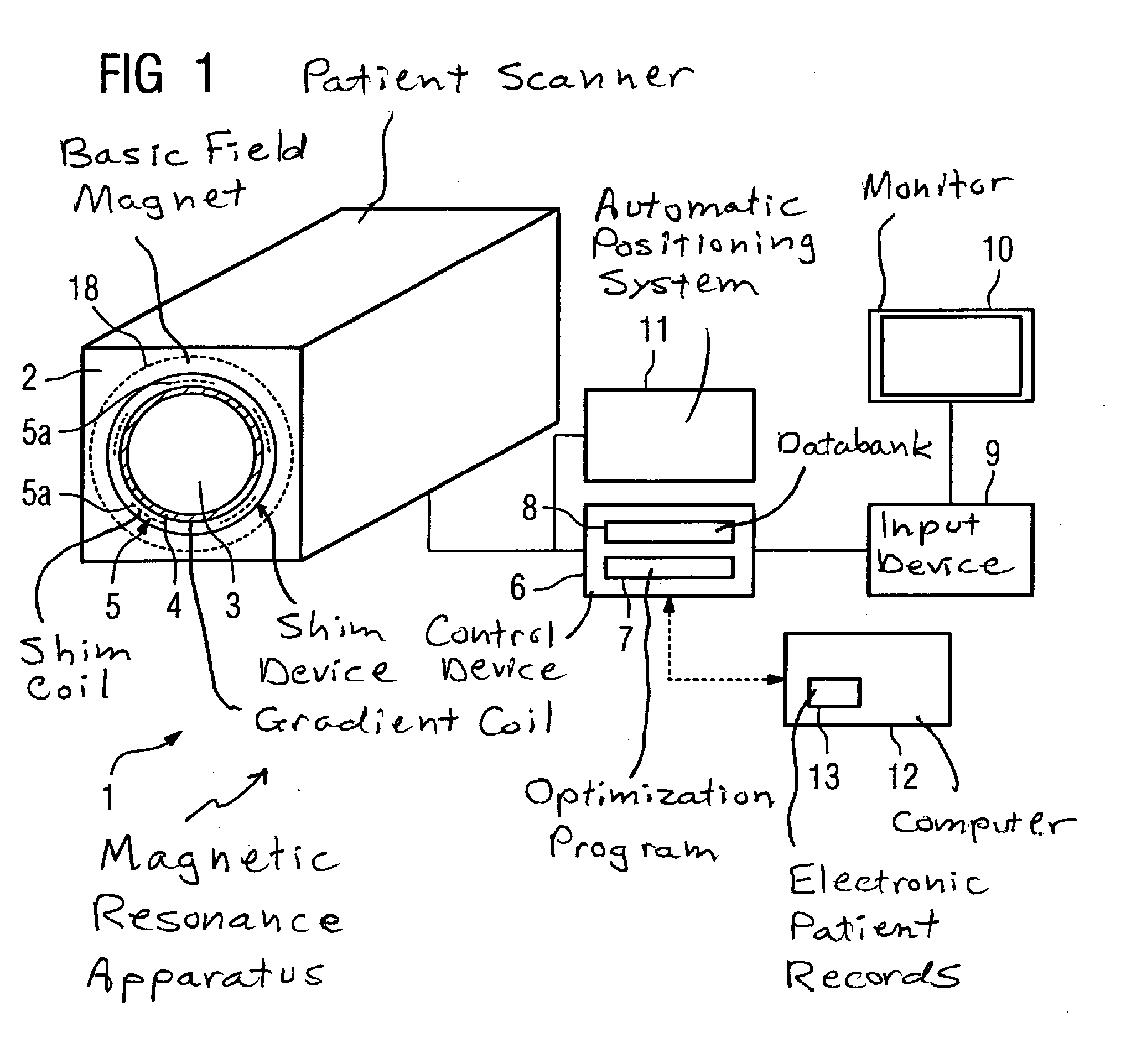
[0032]FIG. 1 shows an inventive magnetic resonance apparatus 1. The apparatus 1 has patient scanner 2 in which the basic field magnet 18 (indicated with dashed lines) is accommodated and that defines a patient receptacle 3. The patient scanner 2 has at least one gradient coil 4 with which a gradient field is generated that serves in a known manner for the spatial resolution (encoding) of the acquired measurement signals. A shim device 5 that has a number of shim coils 5a (indicated with dashed lines) that can be individually fed with current is also arranged between the gradient coils 4 and the basic field magnet 18 in the patient scanner 2. The shim coils 5a serve for the generation of fields that homogenize the magnetic field in the acquisition region. For example, five shim coils 5a can be provided that generate fields corresponding to the five field terms of a spherical function expansion of the second order.

[0033] The magnetic resonance apparatus I also has a control device 6 ...


PUM


Abstract

In a method for adjustment of a shim device of a magnetic resonance apparatus before an image acquisition in a body region that has a volume of interest, a field distribution is measured in a region encompassing the volume of interest produced with a shim device set according to a basic shim data set. A shim data set that is optimized for the volume of interest is determined by a control device starting from the basic shim data set, dependent on the field distribution; and the optimized shim data set is used for adjustment of the shim device. The basic shim data set is selected from a databank of body region-specific input shim data sets.

Description

BACKGROUND OF THE INVENTION [0001] 1. Field of the Invention [0002] The present invention concerns a method for adjustment of a shim device of a magnetic resonance apparatus before an image acquisition in a body region having a volume of interest, wherein a field distribution is measured in an area encompassing the volume of interest produced with a shim device adjusted according to a basic shim data set and wherein a shim data set optimized for the volume of interest is determined by a control device dependent on the field distribution, starting from the basic shim data set and the optimized shim data set is used for adjustment of the shim device. [0003] 2. Description of the Prior Art [0004] For image acquisition in magnetic resonance apparatuses, the homogeneity of the magnetic field in the region of interest is of great importance. Small deviations of the homogeneity can lead to large deviations of the frequency distribution, such that qualitatively substandard images are acquir...

Claims


Application Information

Patent Timeline
IPC IPC(8): G01N24/08A61B5/055
CPCA61B5/055A61B2560/0223A61B5/0037G01R33/3875G01R33/243
Inventor DEWDNEY, ANDREWHARTER, SABRINASCHMITT, FRANZ
Owner SIEMENS HEALTHCARE GMBH
Learn More