Rolling brush component with height capable of being accurately adjusted

A technology of height adjustment mechanism and roller brush, applied in the direction of using tools for cleaning, cleaning methods and utensils, chemical instruments and methods, etc., can solve the problems of large adjustment gap, difficulty in ensuring accuracy, and inability to adjust the non-operating side independently. To achieve the effect of synchronous precise adjustment and high precision

Active Publication Date: 2017-09-15
SUZHOU KZONE EQUIP TECH
View PDF16 Cites 4 Cited by
  • Summary
  • Abstract
  • Description
  • Claims
  • Application Information

AI Technical Summary

Benefits of technology

This technology allows for accurate control over the positioning or movement between two parts that move relative to each other during cleaning operations without being affected by external factors such as gravity. By accurately controlling this motion, these technologies make it easier than previous methods while also improving their overall performance.

Problems solved by technology

This patented technical problem addressed in this patents relates to how to effectively remove small pieces from surfaces made of sheet material for use in electronic components such as displays that require precise placement during manufacturing processes. Current techniques involve manual removal of these tiny debris through rolling brushes which can result in damage to sensitive parts like transistors.

Method used


Image

  • Rolling brush component with height capable of being accurately adjusted
  • Rolling brush component with height capable of being accurately adjusted
  • Rolling brush component with height capable of being accurately adjusted

Examples


Embodiment Construction

[0026] The preferred embodiments of the present invention will be described in detail below with reference to the accompanying drawings.

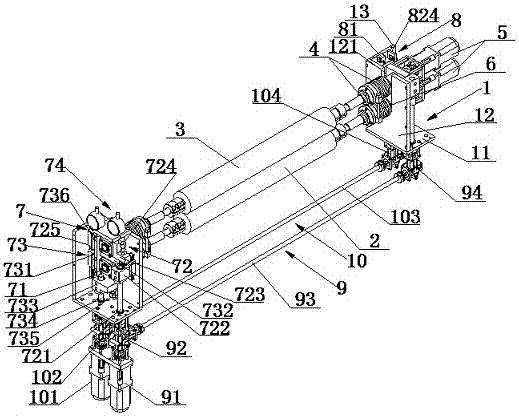
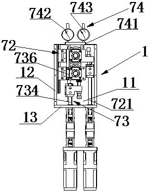
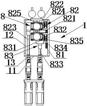
[0027] Such as Figure 1 to Figure 3 The height-adjustable roller brush assembly shown mainly includes a support frame 1, a lower roller brush 2, an upper roller brush 3, a first height adjustment mechanism 7, a second height adjustment mechanism 8, a first synchronous lifting mechanism 9 and The second synchronous lifting mechanism 10 etc.

[0028] Wherein, there are two groups of supporting frames 1, which are arranged on the same horizontal plane and arranged at intervals; each group of supporting frames 1 includes a bottom mounting plate 11, a support vertical plate 12 fixed on the upper surface of the bottom mounting plate 11 and perpendicular to it, and a fixed On the upper surface of the bottom mounting plate 11 and the side plates 13 perpendicular to the bottom mounting plate 11 and the supporting vertical plate 12 respectively, th...


PUM


Abstract

The invention relates to a rolling brush component with a height capable of being accurately adjusted. The rolling brush component comprises two groups of supporting frame bodies which are arranged on a same horizontal plane at an interval, a lower rolling brush which is rotatably installed on the supporting frame bodies, an upper rolling brush which is rotatably installed on the supporting frame bodies and above the lower rolling brush, two first motors which are installed at the end parts of the lower rolling brush and the upper rolling brush respectively and used for driving the lower rolling brush and the upper rolling brush to rotate, a first height adjustment mechanism, a second height adjustment mechanism, a first synchronous lifting mechanism which is connected with a first upper supporting module group and a second upper supporting module group separately and a second synchronous lifting mechanism which is matched with the first synchronous lifting mechanism and is connected with a first lower supporting module group and a second lower supporting module group separately. Therefore, the rolling brush component can realize synchronous accurate adjustment of the two ends of the lower rolling brush and the upper rolling brush and is high in accuracy.

Description


Claims


Application Information

Patent Timeline
Owner SUZHOU KZONE EQUIP TECH
Why Eureka
Try Eureka