Check patentability & draft patents in minutes with Patsnap Eureka AI!

A casing automatic chamfering grinding machine

A grinding machine and bushing technology, which is applied to grinding racks, machine tools suitable for grinding workpiece planes, grinding machines, etc. It can solve the problems of slow chamfering and grinding speed, incapable of chamfering at both ends of the workpiece, and non-continuous work and other issues to achieve the effect of improving production efficiency, reducing human factors, and reducing scrap rate

Active Publication Date: 2019-06-18
CHONGQING UNIV OF POSTS & TELECOMM
View PDF5 Cites 0 Cited by
  • Summary
  • Abstract
  • Description
  • Claims
  • Application Information

AI Technical Summary

Problems solved by technology

However, manual operation has some shortcomings. On the one hand, there are many human factors, and the quality of workpiece chamfering and grinding is uneven. On the other hand, the chamfering and grinding speed is slow, the efficiency is low, the precision is poor, and the finished product is not very high.
In addition, although manual grinding can be bundled together, the chamfering needs to be performed one by one. It is impossible to chamfer both ends of the workpiece at the same time, and it cannot work continuously for a long time.

Method used


Image

  • A casing automatic chamfering grinding machine
  • A casing automatic chamfering grinding machine
  • A casing automatic chamfering grinding machine

Examples


Embodiment Construction

[0021] Embodiments of the present invention will be described in further detail below in conjunction with the accompanying drawings.

[0022] In this embodiment, the orientation or positional relationship indicated by the terms "upper", "lower", "left", "right", "front", "rear", "upper end" and "lower end" are based on the orientation or positional relationship shown in the drawings, It is for the convenience of description only, and does not indicate or imply that the device or element referred to must have a specific orientation, be constructed in a specific orientation, or operate, and thus should not be construed as limiting the present invention.

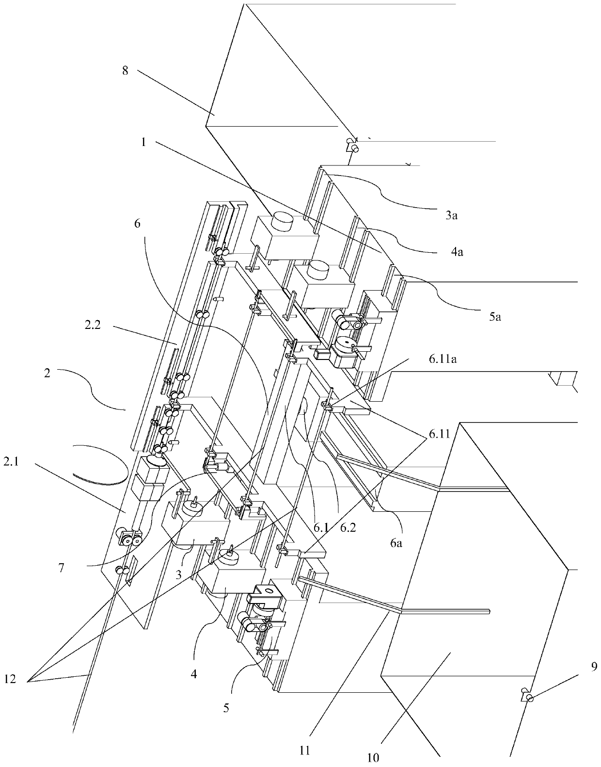
[0023] like figure 1 The casing automatic chamfering grinder shown is used for processing the casing 12, and the casing 12 includes an outer pipe and an inner liner arranged inside the outer pipe. The casing automatic chamfering grinder includes a machine base 1, a feeding device 2 installed on the front end of the machine bas...


PUM


Abstract

The invention discloses an automatic chamfering and grinding machine for sleeves. The automatic chamfering and grinding machine comprises a machine base, a feeding device, two first chamfering devices, two second chamfering devices, two grinding devices and a walking device, wherein the feeding device is arranged at the end part of the machine base, the two first chamfering devices are arranged on the machine base and chamfer the two ends of inner lining pipe bodies of the sleeves at the same time, the two second chamfering devices are arranged on the machine base and chamfer the two ends of outer pipe bodies of the sleeves at the same time, the two grinding devices are arranged on the machine base and grind the two ends of the outer pipe bodies of the sleeves at the same time, and the walking device is arranged on the machine base and is used for clamping the sleeves and moving the sleeves to machining stations; the two first chamfering devices, the two second chamfering devices and the two grinding devices are symmetrically arranged on the two sides of the walking device separately; first sliding rails, second sliding rails and third sliding rails are arranged on the machine base; and the first chamfering devices, the second chamfering devices and the grinding devices are arranged on the first sliding rails, the second sliding rails and the third sliding rails through sliding blocks respectively. The automatic chamfering and grinding machine has the advantages that the chamfering speed for the sleeves is high, continuous work for a long time can be realized, the chamfering quality is high, and the efficiency is high.

Description

technical field [0001] The invention belongs to the field of casing chamfering processing, and in particular relates to an automatic casing chamfering grinder. Background technique [0002] In order to increase the wear resistance and corrosion resistance of the casing, an inner liner is usually provided in the casing. At present, for workpieces, especially casing workpieces with inner liners, manual chamfering and grinding are generally used. However, manual operation has some shortcomings. On the one hand, there are many human factors, and the quality of workpiece chamfering and grinding is uneven. On the other hand, the chamfering and grinding speed is slow, the efficiency is low, the precision is poor, and the finished product is not very high. In addition, although manual grinding can be carried out in multiple bundles, the chamfering needs to be performed one by one, and the two ends of the workpiece cannot be chamfered at the same time, and it cannot work continuously...

Claims


Application Information

Patent Timeline
Patent Type & Authority Patents(China)
IPC IPC(8): B24B7/17B24B41/02B24B41/06B23P23/04
CPCB23P23/04B24B7/17B24B41/02B24B41/06
Inventor 吕霞付陈建罗萍胡体云龚晓光陈勇
Owner CHONGQING UNIV OF POSTS & TELECOMM
Features
  • R&D
  • Intellectual Property
  • Life Sciences
  • Materials
  • Tech Scout
  • Unparalleled Data Quality
  • Higher Quality Content
  • 60% Fewer Hallucinations
Learn More