Buffering device

A buffer device, buffer fluid technology, applied in the direction of spring, shock absorber, spring/shock absorber, etc., can solve problems such as piston damage

Active Publication Date: 2017-09-15
KING SLIDE WORKS CO LTD +1
View PDF18 Cites 5 Cited by
  • Summary
  • Abstract
  • Description
  • Claims
  • Application Information

AI Technical Summary

Problems solved by technology

When the piston rod and the piston are made of different materials, for example, the piston rod is made of metal and the piston is made of plastic, attention must also be paid to the possibility that the piston may be damaged due to long-term use of strong pressure

Method used


Image

  • Buffering device
  • Buffering device
  • Buffering device

Examples


Embodiment Construction

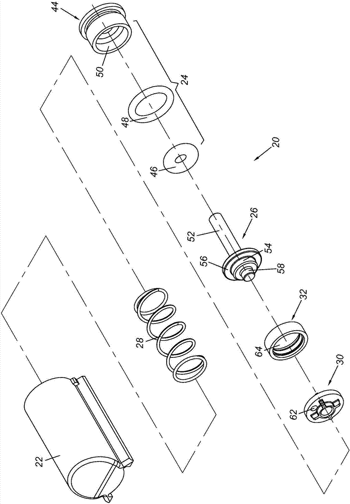
[0026] figure 1 The buffer device 20 according to an embodiment of the present invention includes a cylinder 22 , a covering component 24 , a piston rod 26 and an elastic member 28 . Preferably, the buffer device 20 further includes a base 30 and a control valve 32 .

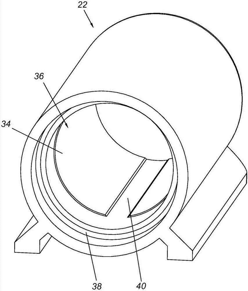
[0027] Such as figure 2 As shown, the cylinder 22 includes an inner wall 34 defining a chamber 36 , and an opening 38 communicating with the chamber 36 . In this embodiment, the cylinder body 22 is substantially cylindrical, and the cylinder body 22 has an annular inner wall 34 . Preferably, the inner wall 34 of the cylinder 22 has a groove 40 . The groove 40 is arranged along the length direction of the cylinder 22 .

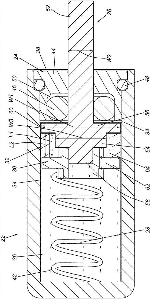
[0028] Such as image 3 As shown, the base 30 and the piston rod 26 are in an initial state relative to the cylinder 22, and the chamber 36 of the cylinder 22 can be filled with a buffer fluid 42 ( image 3 , the buffer fluid 42 is represented by a plurality of black dots).

[0029] The ...


PUM


Abstract

The invention relates to a buffering device. The buffering device comprises a cylinder body, a covering assembly, a piston rod and an elastic piece, wherein the cylinder body comprises a cavity defined by the inner wall of the cylinder body and an opening communicating with the cavity, and the cavity is filled with a buffering fluid; the covering assembly is arranged at the opening adjacent to the cylinder body; the piston rod can move relative to the cylinder body, the piston rod comprises a rod part, an extension part and an expansion part between the rod part and the extension part, the rod part penetrates through the covering assembly, and the width of the expansion part is larger than the width of the rod part; and the elastic piece is arranged in the cavity of the cylinder body and is used for providing elasticity for the piston rod.

Description

technical field [0001] The invention relates to a buffer device, in particular to a buffer device applied to furniture objects. Background technique [0002] Generally speaking, some specific furniture, such as doors or cabinets, will be equipped with cushioning devices. The buffer device can be used to provide a buffering function when the first member is relative to the second member from opening to closing, so as to slow down the force when the first member is closing relative to the second member. For example, US Patent No. US9,021,656B2 discloses a cushioning device for furniture comprising a slide seat (13), a piston (22) and a piston rod (17). Among them, by the case Figure 4 It can be seen from a, 4b that one end of the piston rod (17) is connected to the piston (22), and the piston (22) is located in a chamber (21) of the slide seat (13). [0003] Specifically, according to the related technology of the current buffer device, the piston rod is generally a slender...

Claims


Application Information

Patent Timeline
Patent Type & Authority Applications(China)
IPC IPC(8): F16F9/32F16F9/34
CPCF16F9/3207F16F9/3221F16F9/3235F16F9/34
Inventor 梁秀江陈庚金王俊强
Owner KING SLIDE WORKS CO LTD
Why Eureka
Try Eureka