Multi-fuel nozzle, fuel ejection system and turbine engine thereof

A multi-fuel and nozzle technology, applied in combustion chambers, combustion methods, combustion equipment, etc., can solve the problems of single fuel for turbine engine nozzles, single fuel for turbine engines, etc.

Pending Publication Date: 2017-09-15
艾迪清洁能源(西安)有限公司
View PDF6 Cites 6 Cited by
  • Summary
  • Abstract
  • Description
  • Claims
  • Application Information

AI Technical Summary

Problems solved by technology

[0006] The purpose of the present invention is to provide a multi-fuel nozzle to solve the technical problem that the turbine engine nozzle in the prior art can only be adapted to a single fuel
[0007] Another object of the present invention is to provide a fuel injection system and a turbine engine with the above-mentioned multi-fuel nozzle, to solve the technical problem that the turbine engine in the prior art can only use a single fuel combustion work

Method used


Image

  • Multi-fuel nozzle, fuel ejection system and turbine engine thereof
  • Multi-fuel nozzle, fuel ejection system and turbine engine thereof
  • Multi-fuel nozzle, fuel ejection system and turbine engine thereof

Examples


Embodiment 1

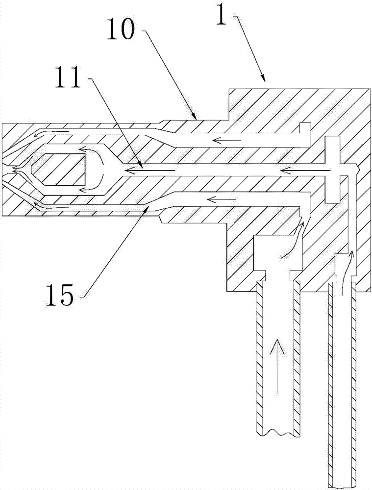
[0055] Such as figure 1 As shown, the multi-fuel nozzle 1 provided in this embodiment includes a nozzle body 10 in which a first fuel flow passage 11 and a second fuel flow passage 15 are provided. On a cross-section perpendicular to the fuel flow direction, The first fuel flow passage 11 is arranged in the middle, and several second fuel flow passages 15 are arranged in the circumferential direction of the first fuel flow passage 11.

[0056] A plurality of second fuel flow passages 15 are evenly arranged in the circumferential direction of the first fuel flow passage 11.

[0057] Among them, the number of the second fuel flow passage 15 is 3-20.

[0058] Preferably, the first fuel flow channel 11 has a narrower aperture at the end of its fuel injection. The second fuel flow path 15 narrows the aperture at the end of the fuel injection.

[0059] The second fuel flow passage 15 approaches the first fuel flow passage 11 in the radial direction of the nozzle body 10 at the end of the f...

Embodiment 2

[0064] The structure of this embodiment is basically the same as that of embodiment 1, and the difference lies in:

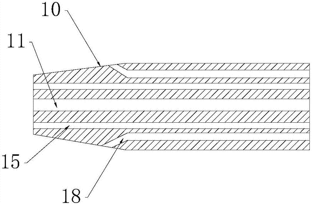
[0065] Such as figure 2 As shown, the nozzle body 10 is also provided with a number of third fuel flow passages 18, in a cross section perpendicular to the fuel flow direction, a number of third fuel flow passages 18 are provided in the circumferential direction of the first fuel flow passage 11, In the radial direction, the second fuel flow passage 15 is provided between the first fuel flow passage 11 and the third fuel flow passage 18.

[0066] That is, on a cross-section perpendicular to the fuel flow direction, the first fuel flow channel 11, the second fuel flow channel 15 and the third fuel flow channel 18 are sequentially arranged from the inside to the outside.

[0067] The third fuel flow path 18 is away from the first fuel flow path 11 outward in the radial direction of the nozzle body 10 at the end of the fuel injection. That is, the fuel outlet of the thi...

Embodiment 3

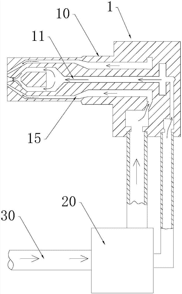
[0070] Such as image 3 As shown, the embodiment of the present invention also discloses a fuel injection system using the above-mentioned multi-fuel nozzle 1, which further includes: a fuel supply pipe 30 and a fluid distribution device 20;

[0071] The fuel supply pipeline 30 is connected to the multi-fuel nozzle 1 through the fluid distribution device 20;

[0072] The fluid distribution device 20 is used to split the fuel from the fuel supply line 30 into the first fuel flow passage 11 and the second fuel flow passage 15.

[0073] A regulating valve (not shown) is provided in the fluid distribution device 20 for dividing or proportionally distributing the fuel from the fuel supply line 30 to the first fuel flow passage 11 and the second fuel flow passage 15.

[0074] By controlling and adjusting the regulating valve on the fluid distribution device 20, all the fuel from the fuel supply pipe 30 can be diverted to the first fuel flow passage 11 or the second fuel flow passage 15, and ...


PUM


Abstract

The invention provides a multi-fuel nozzle, a fuel ejection system and a turbine engine thereof. The multi-fuel nozzle comprises a nozzle body, wherein a first fuel flowing channel and second fuel flowing channels are formed in the nozzle body; and on a section vertical to a fuel flowing direction, the first fuel flowing channel is formed in the middle, and the plurality of second fuel flowing channels are formed in the circumferential direction of the first fuel flowing channel. Many fuel flowing channels are formed in the nozzle body of the multi-fuel nozzle provided by the invention, and fuels can be distributed into the different fuel flowing channels in proportion by virtue of a fluid distribution device and ejected according to the types of the fuels and the combustion need of the turbine engine, so that the combustion need of the many fuels can be met.

Description

Technical field [0001] The invention relates to the technical field of turbine engines, in particular to a multi-fuel nozzle, a fuel injection system and a turbine engine thereof. Background technique [0002] At present, a turbine engine (or Turbine) is a form of engine that uses rotating parts to extract kinetic energy from a fluid passing through it, and is a type of internal combustion engine. It is often used as an engine for airplanes and large ships or vehicles. [0003] Turbine engines are usually equipped with compressor (Compressor), combustion chamber (Cumbustion), turbine (Turbine) three parts. The compressor is usually divided into a low-pressure compressor (low-pressure section) and a high-pressure compressor (high-pressure section). The low-pressure section sometimes also has the function of an intake fan to increase the intake air volume. The incoming airflow is compressed into a high-density, high-density compressor in the compressor. High-pressure, low-speed air...

Claims


Application Information

Patent Timeline
Patent Type & Authority Applications(China)
IPC IPC(8): F23R3/38
CPCF23R3/38
Inventor 张建勇胡滨
Owner 艾迪清洁能源(西安)有限公司
Why Eureka
Try Eureka