Control apparatus and control method

a control apparatus and control method technology, applied in the field of control apparatus and control method, can solve problems such as difficulty in appropriately adjusting the tilt angle, and achieve the effect of smooth setting of parameters

Active Publication Date: 2019-11-14
CANON KK
View PDF6 Cites 5 Cited by
  • Summary
  • Abstract
  • Description
  • Claims
  • Application Information

AI Technical Summary

Benefits of technology

[0005]The present invention is directed to a control apparatus capable of smoothly setting parameters of an imaging apparatus that has a rotation device for tilting the angle of its imaging element.

Problems solved by technology

This changes the focus position and accordingly makes it difficult to adjust the tilt angle appropriately.

Method used


Image

  • Control apparatus and control method
  • Control apparatus and control method
  • Control apparatus and control method

Examples


Embodiment Construction

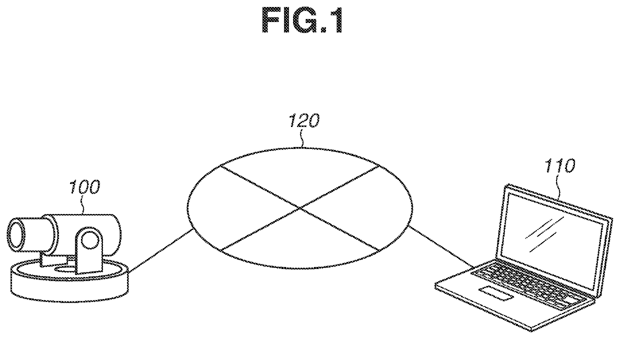
[0018]FIG. 1 is an overall view of a monitoring system according to a first exemplary embodiment. A monitoring camera 100 and a control apparatus 110 are communicably connected with each other via a network. The control apparatus 110 transmits various commands to the monitoring camera 100. The monitoring camera 100 transmits responses to those commands to the control apparatus 110. In the monitoring camera 100, zoom and focus can be adjusted.

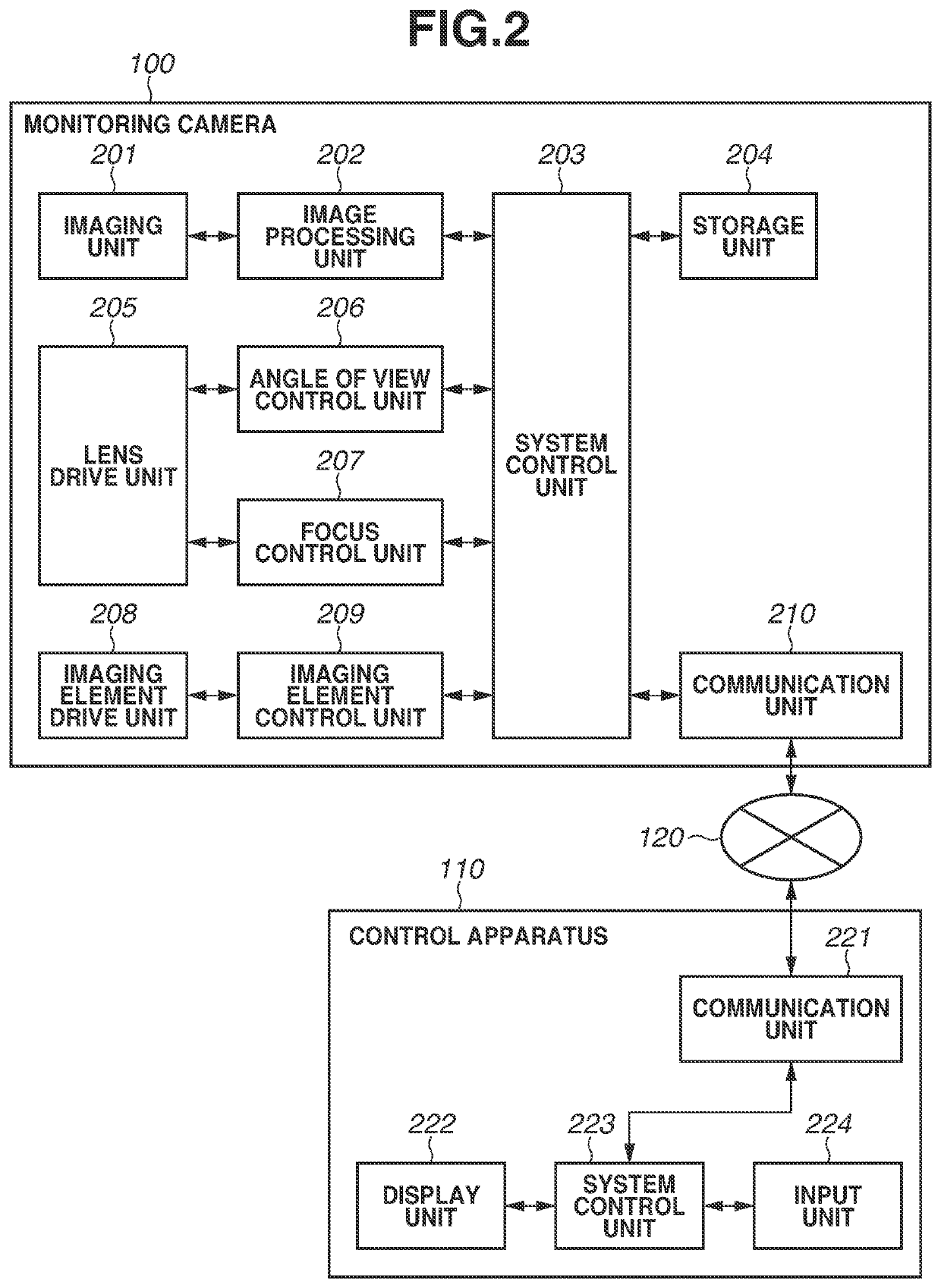
[0019]FIG. 2 is a block diagram illustrating a hardware configuration of the monitoring system. The monitoring camera 100 includes an imaging unit 201, an image processing unit 202, a system control unit 203, and a storage unit 204. The monitoring camera 100 further includes a lens drive unit 205, an angle of view control unit 206, a focus control unit 207, an imaging element drive unit 208, an imaging element control unit 209, and a communication unit 210.

[0020]The imaging unit 201 includes a lens and an imaging element, and performs imaging of...


PUM


Abstract

A control apparatus for an imaging apparatus having a drive unit for tilting of an imaging element includes a tilt angle setting unit configured to set a tilt angle, and a control unit configured to perform control so as not to change a parameter that affects the tilt angle during tilt angle setting.

Description

BACKGROUND OF THE INVENTIONField of the Invention[0001]The present invention relates to a control apparatus having a drive unit for rotating an imaging element, and to a control method for the imaging apparatus.Description of the Related Art[0002]Conventionally, there has been a case where a monitoring camera is installed at a high position (e.g. overhead camera), and the optical axis of the camera is directed obliquely downward, so that the monitoring camera monitors people walking on a road and captures an image of a car and the number plate of the car. In this case, the focal plane of the camera (which, as will be understood by those skilled in the art, lies on a plane perpendicular to the camera's optical axis) may lie on a different plane to the object (e.g. person / car) to be imaged. That is, the plane of the object to be imaged may not be inclined perpendicularly to the optical axis of the camera when the camera views / images the object at an angle from an elevated position. Ac...

Claims


Application Information

Patent Timeline
Patent Type & Authority Applications(United States)
IPC IPC(8): H04N5/232
CPCH04N5/23299H04N5/23203H04N7/18H04N23/67H04N23/695H04N23/662H04N23/62H04N23/631H04N23/635H04N23/63H04N23/661H04N23/66
Inventor NIGA, SHOTA
Owner CANON KK
Why Eureka
Try Eureka