Optical disc device and recording medium

a technology of optical discs and recording media, which is applied in the direction of data recording, digital signal error detection/correction, instruments, etc., can solve the problems of significant disturbance of the reproduction rf signal, power shortage or power excess, and long setting time, so as to achieve smooth laser power and smooth laser power setting

Inactive Publication Date: 2005-12-29
SANYO ELECTRIC CO LTD
View PDF4 Cites 5 Cited by
  • Summary
  • Abstract
  • Description
  • Claims
  • Application Information

AI Technical Summary

Benefits of technology

[0011] The present invention has been made to solve the above-mentioned problems. An object of the present invention is to provide an optical disc device capable of smoothly and adequately setting power even when an outgoing wavelength is shifted, and a recording medium used for the optical disc device.
[0020] According to the present invention, even when the wavelength of the outgoing laser light from the semiconductor laser is shifted due to a change in temperature or the like, the laser power can be suitably corrected to adequate laser power according to the shifted wavelength. When the present invention is applied to laser power setting using a β method, trial writing is performed at adequate laser power to which initial power set in advance is corrected as appropriate. Therefore, the laser power can be smoothly set. In addition, even when recording operation is stopped for a long time after laser power setting and then restarted, a wavelength shift caused during a period from stop to restart is estimated, so that previously set laser power can be corrected to adequate laser power to obtain laser power for next recording operation. Thus, laser power can be smoothly set to adequate laser power without retrial writing.

Problems solved by technology

Therefore, when the initial set power is used without changing in trial writing, power shortage or power excess may occur.
When the degree of power shortage or power excess is large, the reproduction RF signal is significantly disturbed.
However, such power setting requires a long time and wastes a trial wiring area.

Method used


Image

  • Optical disc device and recording medium
  • Optical disc device and recording medium
  • Optical disc device and recording medium

Examples


embodiment 1

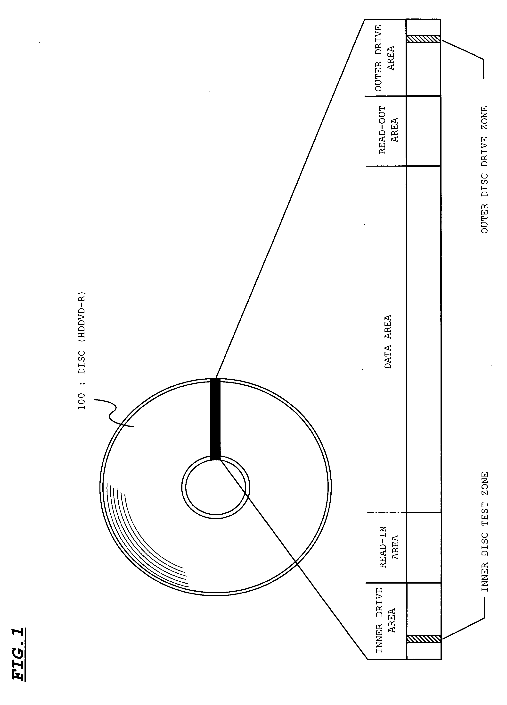
[0029]FIG. 1 shows a structure of a disc (HDDVD-R) according to this embodiment. As shown in FIG. 1, a disc 100 is divided into an inner drive area, a read-in area, a data area, a read-out area, and an outer drive area in a radius direction. The inner drive area and the outer drive area each are classified into various zones. Of the various zones, an inner disc test zone and an outer disc test zone are used to perform initial laser power setting (optimum write power control (OPC)).

[0030] In the disc 100, spiral grooves are formed from the inner circumference to the outer circumference. Data is recorded in the grooves. Here, the grooves are meandered (wobbled) in the radius direction. Address information is held by the wobble. That is, a phase modulation section which is called an address in pre-groove (ADIP) is inserted into a monotonic meandering section at regular intervals. When the phase modulation section is scanned with a beam, address information on the grooves are read base...

embodiment 2

[0058] In Embodiment 1, the initial power Pw0 for OPC is corrected using the wavelength compensation table. The wavelength compensation table can be also used to adjust the recording laser power Pp set during the OPC.

[0059] For example, assume that the recording laser power is set during the OPC and then not reset for a long time. When the recording operation is performed again, the recording laser power Pp is adjusted based on the current ambient temperature and the wavelength compensation table.

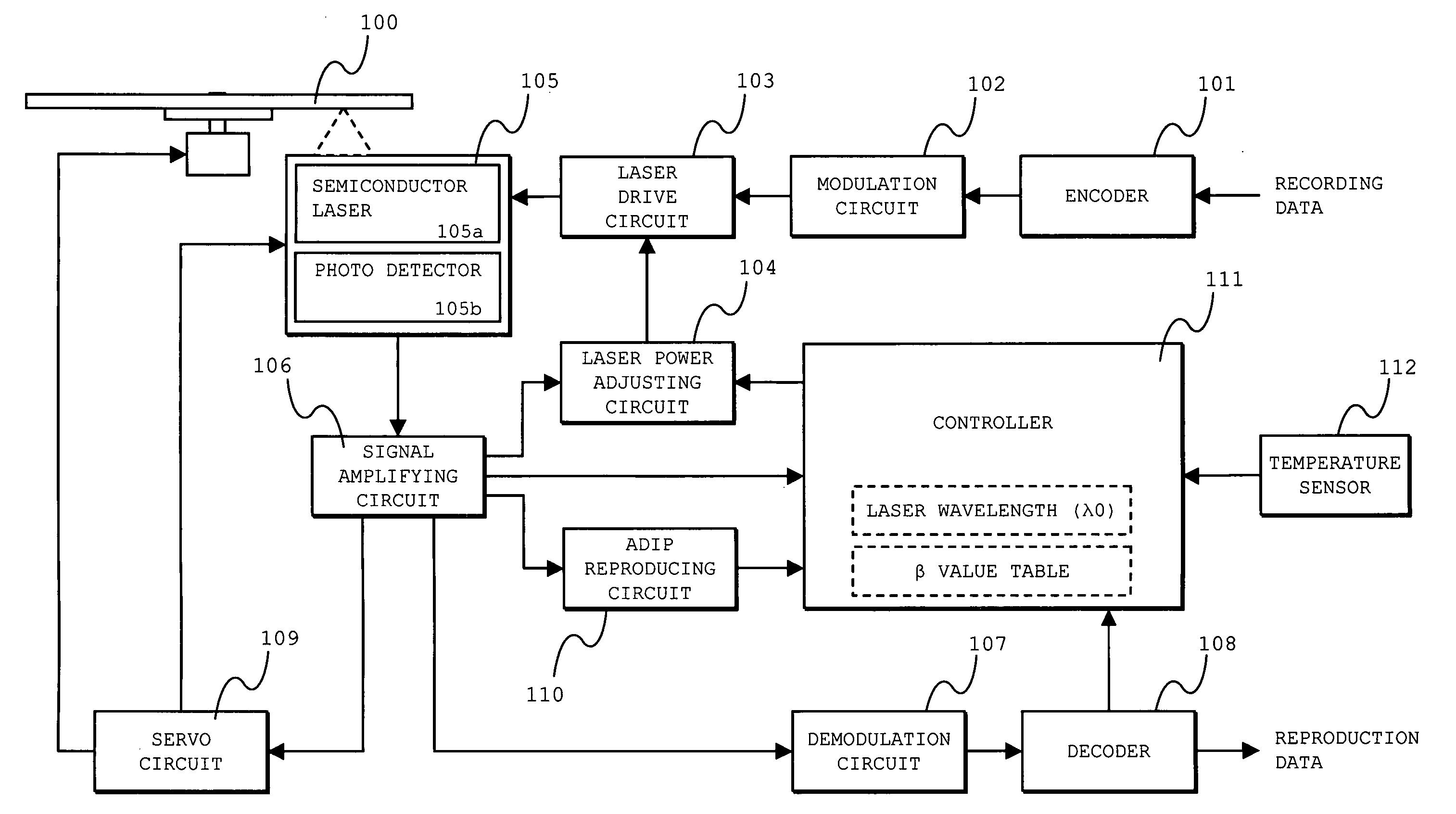
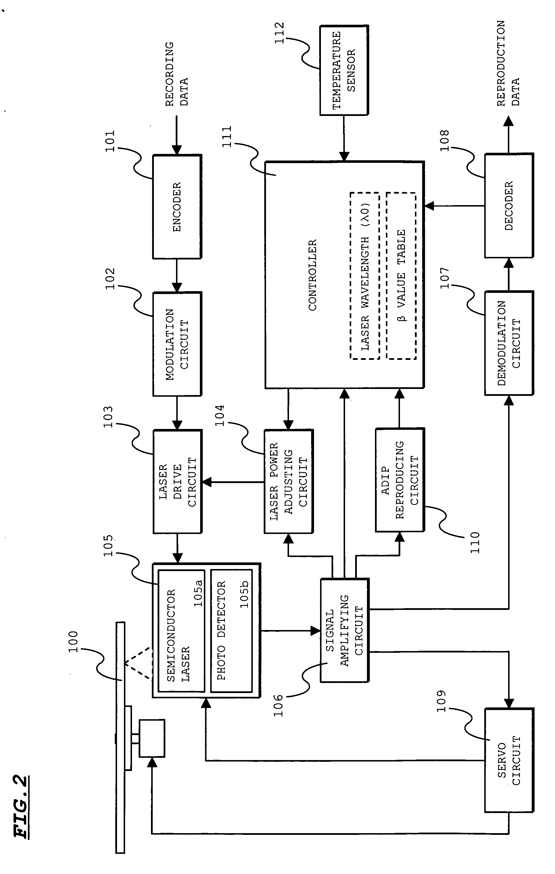
[0060]FIG. 5 shows a processing flow in such a case. First, the controller 111 obtains the current temperature T1 from the temperature sensor 112 (Step S201) and calculates the difference ΔT between the obtained temperature T1 and the ambient temperature T0 (room temperature in this embodiment: 25° C.) of the semiconductor laser 105a in which the wavelength of the outgoing laser light is the reference wavelength λ0 (Step S202). Next, the shift amount Δλ from the reference wavelength λ0 is...


PUM

PropertyMeasurementUnit
wavelengthsaaaaaaaaaa
reflectanceaaaaaaaaaa

Abstract

Provided is an optical disc device capable of smoothly and adequately setting laser power even when an outgoing wavelength is shifted. A wavelength compensation table for associating a laser wavelength with a compensation factor is recorded in advance in a disc using a wobble, a pit, or the like. When the disc is set, a controller reads out the wavelength compensation table from the disc and causes an internal memory thereof to store it. A wavelength of outgoing laser light is determined based on temperature information supplied from a temperature sensor during OPC. Compensation factors α1 and α0 respectively corresponding to the determined wavelength and a reference wavelength are obtained from the wavelength compensation table. Initial power Pw1 for OPC to be set is calculated using initial power Pw0 and the compensation factors α1 and α0 by Pw1=Pw0×(α1 / α0).

Description

BACKGROUND OF THE INVENTION [0001] 1. Field of the Invention [0002] The present invention relates to an optical disc device and a recording medium, and more particularly is suitable to adjust laser power. [0003] 2. Description of the Related Art [0004] In an optical disc device that performs recording and reproduction on an optical disc such as a CD-R (compact disc-recordable) or a DVD-R (digital versatile disc-recordable), trial writing is performed on a preset laser power adjustment area to set recording laser power to optimum power. Such laser setting is generally performed by a β method. That is, trial writing is performed on the laser power adjustment area at predetermined power. A β value is obtained from an asymmetry of a reproduction RF signal. The obtained β value is compared with a target β value required for the disc to set recording laser power. [0005]FIG. 6 shows a β value calculation method. As shown in FIG. 6, the β value is obtained by calculation of (Itop+Ibtm) / (Ito...

Claims


Application Information

Patent Timeline
Patent Type & Authority Applications(United States)
IPC IPC(8): G11B7/00
CPCG11B7/1267
Inventor KAKAO, KENJINAKATANI, MORIO
Owner SANYO ELECTRIC CO LTD
Why Eureka
Try Eureka