
A self-protected battery

A self-protection, battery technology, applied in the direction of batteries, secondary batteries, battery pack components, etc., can solve the problems of not cooling the battery, short battery life, detection errors, etc., to achieve high safety and good practicability , the effect of simple battery structure

Active Publication Date: 2020-01-07
LUSHAN COLLEGE OF GUANGXI UNIV OF SCI & TECH
View PDF4 Cites 0 Cited by
  • Summary
  • Abstract
  • Description
  • Claims
  • Application Information

AI Technical Summary

Problems solved by technology

[0002] During the use of existing batteries, their operating temperature fluctuates widely, and the performance of the battery is also different under different temperature environments. Among them, when the battery is in a high temperature state, the battery can store and release The energy density is very high, but the calorific value is also large
As we all know, the higher the temperature of the battery, the shorter the life of the battery, and when the internal temperature is too high, the battery will explode or catch fire. Therefore, how to ensure that the battery operates under the normal temperature range is an urgent need to solve in the battery industry. The problem
[0003] At present, the temperature of the battery is monitored by detecting the temperature outside the battery, and the temperature of the battery is cooled by adding a cooling device installed on the outside. Although this method reduces the possibility of high-temperature explosion of the battery to a certain extent, due to the external temperature of the battery and There is a certain difference in the internal temperature. Often when the external temperature of the battery is still normal, the internal temperature of the battery is already higher than the upper limit of its operating temperature range. In this case, the battery is likely to explode, so the existing external temperature detection method still has certain detection errors and limitations.

Method used


Image

  • A self-protected battery
  • A self-protected battery

Examples


Embodiment Construction

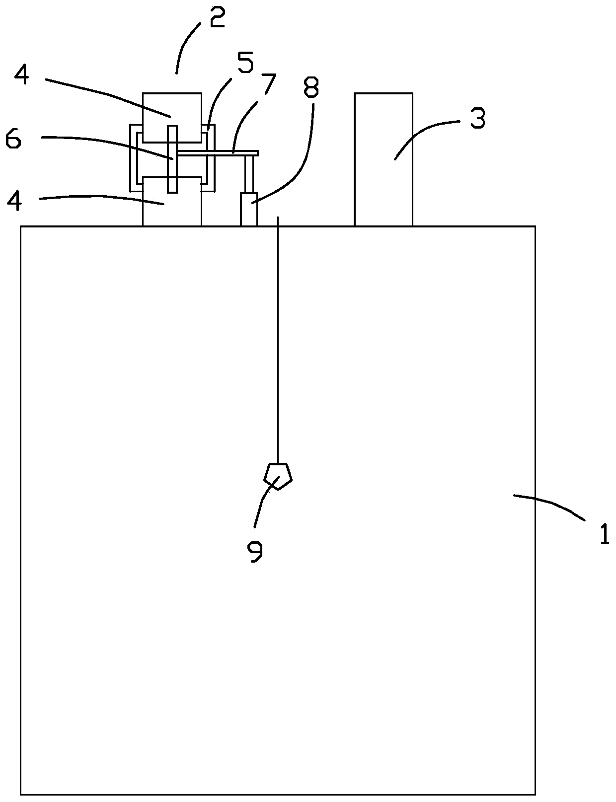
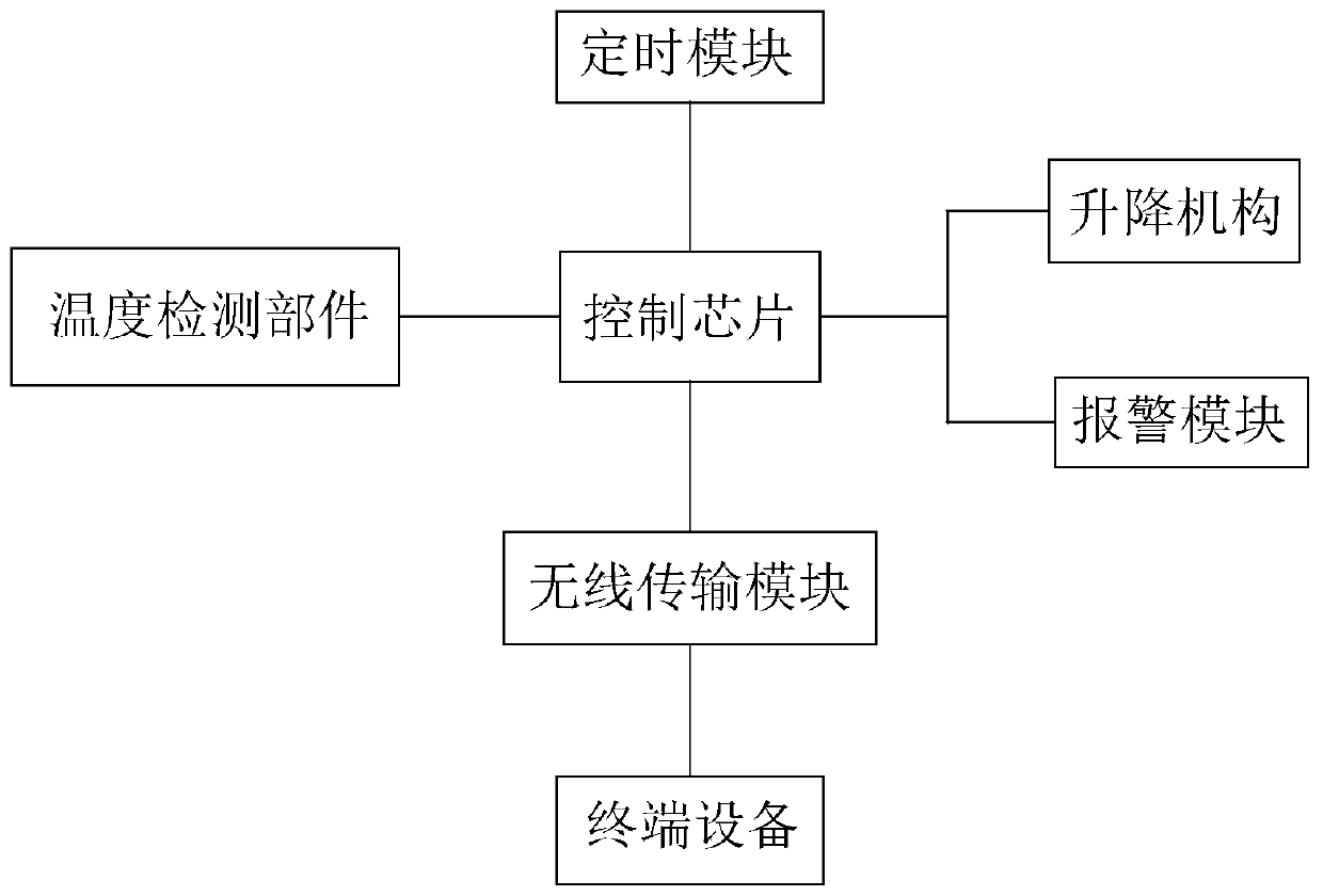
[0022] see figure 1 and figure 2 , in a preferred embodiment of the present invention, a self-protection battery includes a battery body 1 with positive and negative poles, a control chip all installed on the battery body 1, a lifting mechanism 8 and a temperature Detection part 9. At least one of the positive pole 2 and the negative pole 3 of the battery body 1 is composed of two sub-columns 4, one of the two sub-columns 4 is connected to the battery main body, and the other is used to connect peripheral equipment, and there is an inter-electrode gap between the two sub-columns 4 , and communicate through the pole connecting body 6; the pole connecting body 6 is made of conductive material, inserted into the interior of the sub-column 4, and slidably connected with the sub-column 4. The lifting mechanism 8 is located on one side of the pole connecting body 6 and is connected to the pole connecting body 6; the temperature detecting end of the temperature detecting part 9 ex...


PUM


Abstract

The invention provides a self-protection battery and belongs to the technical field of a battery. The battery comprises a battery main body, wherein at least one of an anode pole and a cathode pole of the battery main body is composed of two sub-poles; one of the two sub-poles is connected with the battery main body; the other sub-pole is connected with an external device; an inter-pole gap exists between the two sub-poles; the two sub-poles are connected with each other through a pole connector; the pole connector is made from a conductor material, is inserted into the sub-poles and is in sliding connection with the sub-poles; the battery further comprises a control chip, a lifting mechanism and a temperature measuring component which are arranged on the battery main body; the control chip is respectively connected with the lifting mechanism and the temperature measuring component; the lifting mechanism is located on one side of the pole connector and is connected with the pole connector; a temperature measuring end of the temperature measuring component is inserted into the battery main body. The self-protection battery can detect the temperature in the battery and can automatically break circuit when the interior temperature of the battery is ultrahigh.

Description

technical field [0001] The invention relates to the technical field of batteries, in particular to a self-protecting battery. Background technique [0002] During the use of existing batteries, their operating temperature fluctuates widely, and the performance of the battery is also different under different temperature environments. Among them, when the battery is in a high temperature state, the battery can store and release The energy density is very high, but the heat generation is also very large. As we all know, the higher the temperature of the battery, the shorter the life of the battery, and when the internal temperature is too high, the battery will explode or catch fire. Therefore, how to ensure that the battery operates under the normal temperature range is an urgent need to solve in the battery industry. The problem. [0003] At present, the temperature of the battery is monitored by detecting the temperature outside the battery, and the temperature of the bat...

Claims


Application Information

Patent Timeline
Patent Type & Authority Patents(China)
IPC IPC(8): H01M2/34H01M10/48
CPCH01M10/486H01M2200/10H01M50/581Y02E60/10
Inventor 梁锡铅农春香覃晓捷
Owner LUSHAN COLLEGE OF GUANGXI UNIV OF SCI & TECH
Learn More