
An isometric molding machine

A molding machine, isometric technology, applied in the printing press, rotary printing machine, printing, etc., can solve the problem of difficult isometric printing of the molding machine

Active Publication Date: 2019-08-20
叶纪友
View PDF9 Cites 0 Cited by
  • Summary
  • Abstract
  • Description
  • Claims
  • Application Information

AI Technical Summary

Problems solved by technology

[0003] However, in the printing process of the molding press of the prior art, it is difficult for the molding press to realize equidistant printing.

Method used


Image

  • An isometric molding machine
  • An isometric molding machine
  • An isometric molding machine

Examples


specific Embodiment approach

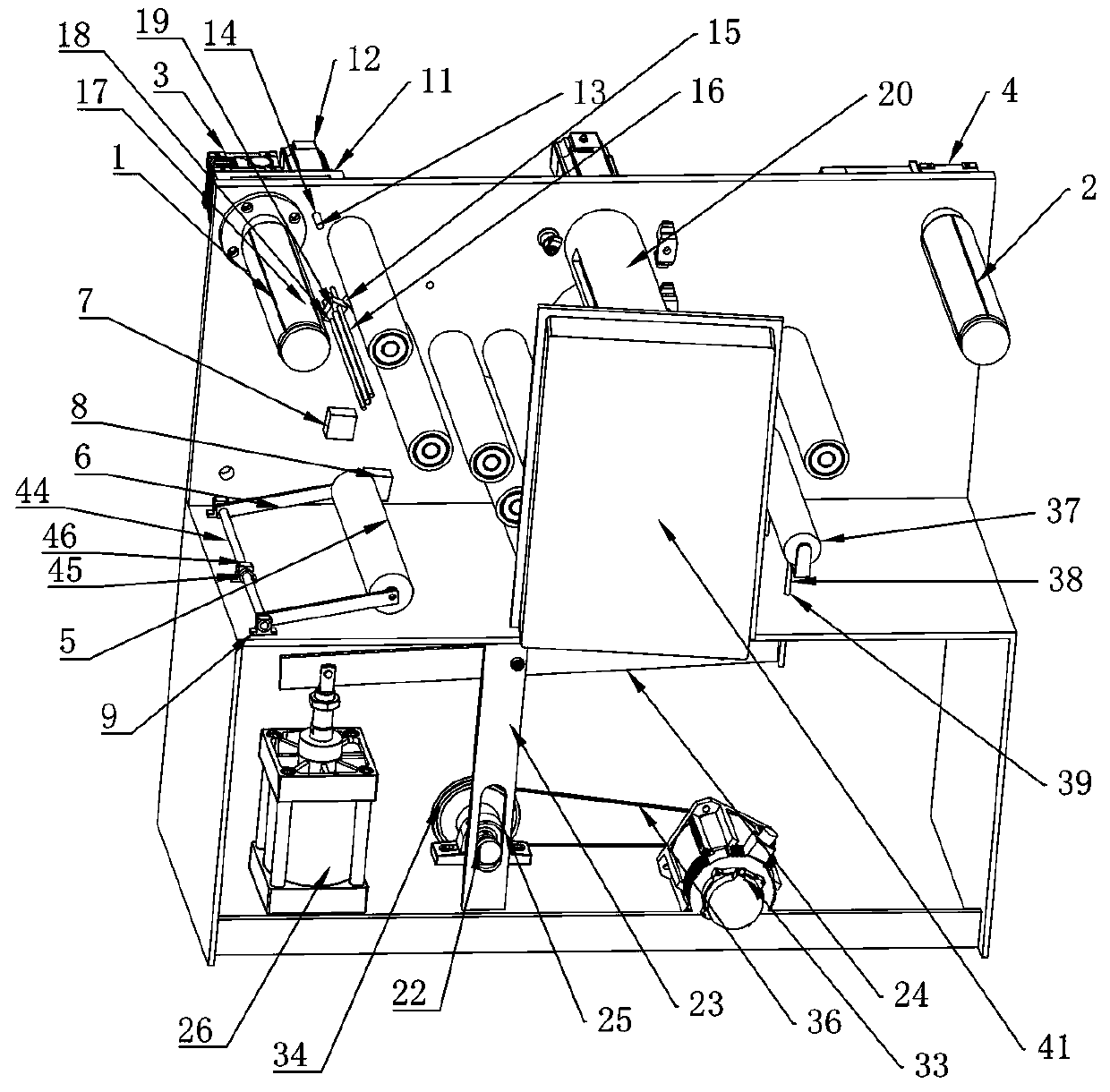
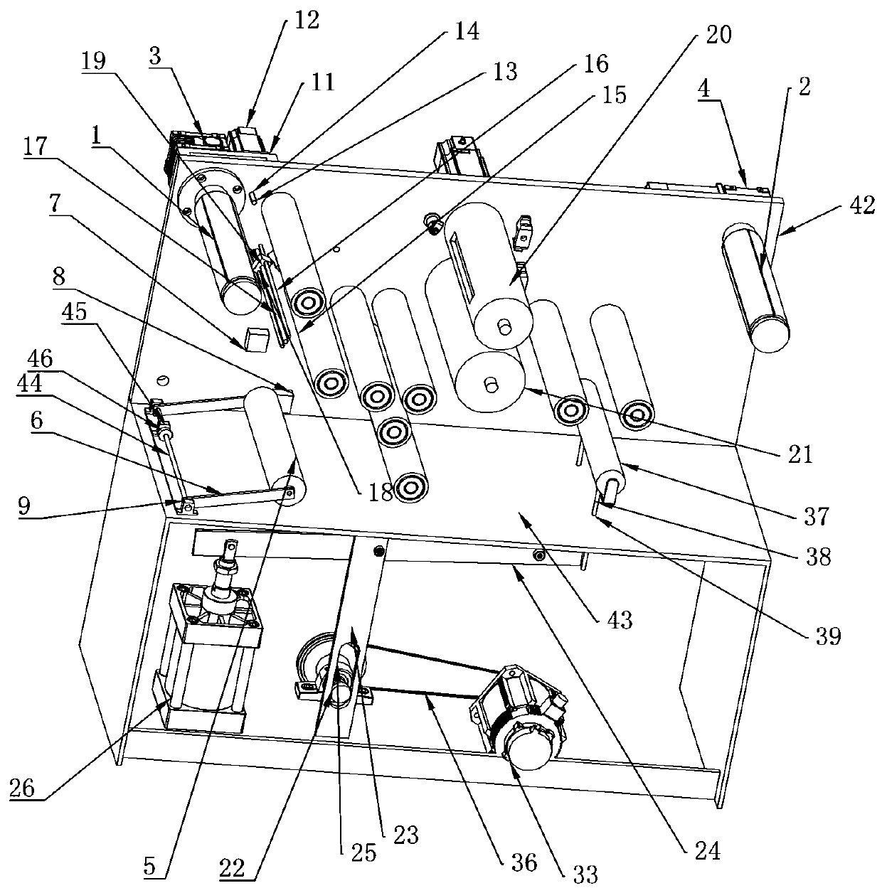
[0033]As an improved specific embodiment: the side of the installation plate 42 facing away from the unwinding roller 1 is provided with an adjustment plate 11, the first driving mechanism is arranged on the adjustment plate 11, and the adjustment plate 11 is also provided with There is a rotating motor 12, the output end of the rotating motor 12 is provided with a first screw 13, the mounting plate 42 is provided with a first screw hole 14, and the first screw 13 is threaded on the first screw hole 14 A threaded screw structure is formed.

[0034] Through the above-mentioned technical scheme, in the process of use, after the deflection of the lower roll film, the first screw 13 on the rotating motor 12 can be driven by driving the rotating motor 12. Since the first screw 13 and the first screw hole 14 form a The structure of a threaded screw can adjust the position of the adjusting plate 11 relative to the mounting plate 42, and the first driving mechanism 3 is located on the...

Embodiment approach

[0037] As an improved specific embodiment: the mounting plate 42 is provided with a mounting rod 16 and a second screw rod 17, and the sensor 15 is provided with a mounting hole 18 for the mounting rod 16 to pass through and a screw thread for the second screw rod 17. connected to the second screw hole 19 , the second screw rod 17 is rotatably connected to the mounting plate 42 .

[0038] By installing the sensor 15 on the installation rod 16, the sensor 15 can be installed at any position of the installation rod 16, so that it can be adjusted as required. When adjusting the position of the sensor 15, the second screw rod can be rotated directly, so that the position of the sensor 15 can be adjusted. This adjustment structure is simple in structure and easy to operate. As an improved specific embodiment: it also includes an upper pressing roller 20 and a lower pressing roller 21 for printing patterns, the upper pressing roller 20 is arranged between the unwinding roller 1 and ...


PUM


Abstract

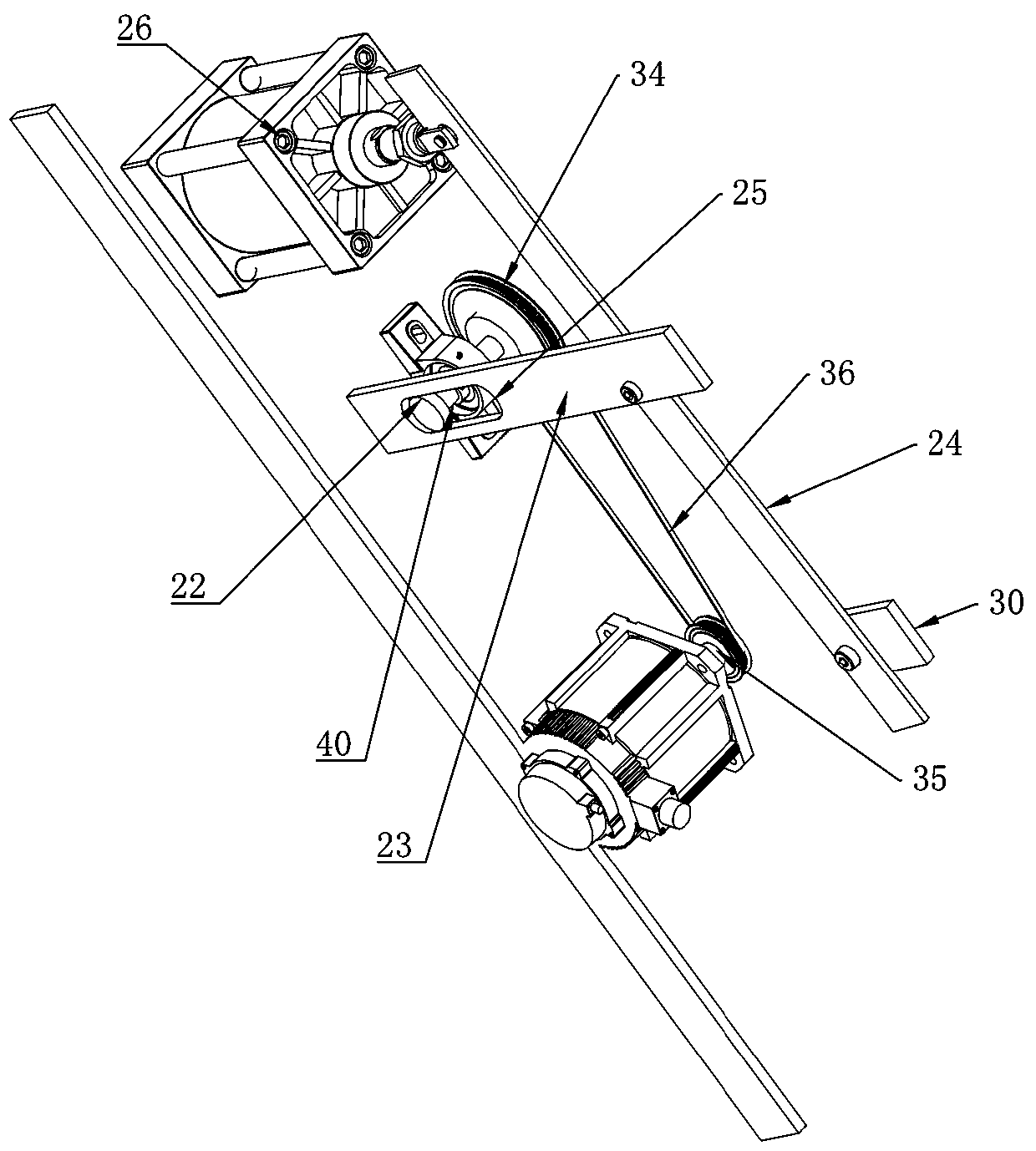
The invention discloses an equal-distance molding press. The equal-distance molding press comprises a mounting plate and a bottom plate. An unwinding roller and a winding roller are arranged on the mounting plate. A first driving mechanism for driving the unwinding roller to rotate and a second driving mechanism for driving the winding roller to rotate are arranged on the unwinding roller and the winding roller correspondingly. A moving roller is further arranged on the mounting plate. The moving roller is connected to a connecting rod in a rolling mode. The connecting rod is hinged to the bottom plate. A coiled film on the unwinding roller passes the bottom of the moving roller and goes into the winding roller. The moving roller makes contact with the coiled film all the time. A first proximity switch and a second proximity switch are further arranged on the mounting plate. The first proximity switch is located above the second proximity switch. Through the scheme, equal-distance conveying during winding and unwinding can be realized; the function of quantitative unwinding in the unwinding process can be achieved as well; meanwhile, it can be guaranteed that the coiled film is tensioned and cannot get loosened in the unwinding and winding process.

Description

technical field [0001] This invention relates to a molding machine, and more particularly to an isometric molding machine. Background technique [0002] The laser film is a film with holographic information on the surface, which is embossed on a base film such as PET by a laser molding machine. In the printing process of the laser film, it is mainly realized by a molding machine. The Chinese patent No. CN200920253674.7 in the prior art discloses a seamless laser molding machine, which consists of an unwinding device, a front molding machine, a rear molding machine and a winding device. The front molding machine and the rear molding machine are respectively Molding rollers are installed, and the holographic pattern master is installed on the molding rollers of the front and rear molding machines respectively. The front and rear version rollers are both hollow cylinders, and the inner chambers are respectively equipped with hot oil chambers and cold oils along the axial direc...

Claims


Application Information

Patent Timeline
Patent Type & Authority Patents(China)
IPC IPC(8): B41F19/02
Inventor 叶纪友
Owner 叶纪友
Learn More