Power supplying system for electric car

A technology for electric vehicles and power supply systems, applied in electric vehicles, electric vehicle charging technology, motor vehicles, etc., can solve the problems of long time for halfway parking and charging, traffic congestion, and no electricity to break down, etc., and achieve the effect of easy transformation.

Active Publication Date: 2017-09-19
安徽鸿创新能源动力有限公司
View PDF5 Cites 5 Cited by
  • Summary
  • Abstract
  • Description
  • Claims
  • Application Information

AI Technical Summary

Problems solved by technology

Even if driving a short distance in the city, users need to pay attention to the remaining power of the electric vehicle, otherwise it is easy to break down due to no electricity halfway
The scheme of setting up charging equipment on the roadside similar to two-wheeled battery vehicles is not very suitable for electric vehicles. On the one hand, the footprint ...

Method used


Image

  • Power supplying system for electric car
  • Power supplying system for electric car
  • Power supplying system for electric car

Examples


Embodiment 1

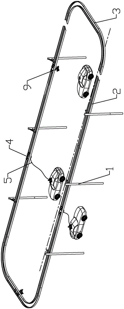
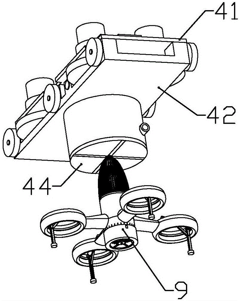
[0062] according to Figure 1 to Figure 17 As shown, the present embodiment is a power supply system for electric vehicles, including a plurality of power transmission poles 1 fixedly installed on both sides of the road, power transmission guide rails 2 installed between each power transmission poles, rolling or slidingly installed on the power transmission guide rails The guide rail car 4 that is electrically connected with the power transmission guide rail, the aircraft 9 that can be parked on the electric vehicle and is electrically connected with the electric vehicle, and is connected between the guide rail car and the aircraft to transmit electric energy from the power transmission guide rail to the electric vehicle. of wire 5.

[0063] At least two groups of reversing guide rails 3 for the reversing of guide rail cars are connected between two groups of transmission guide rails on both sides of the road; It includes a vertical plate for guiding and a horizontal plate in...

Embodiment 2

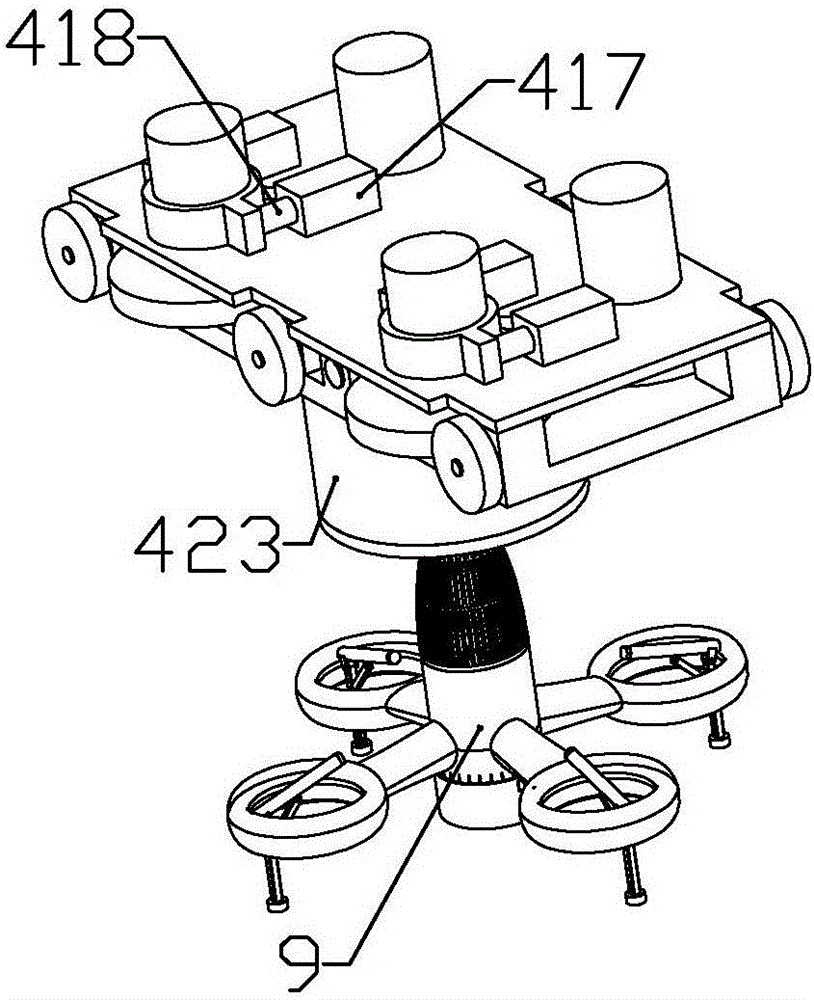
[0094] combine Figure 18 to Figure 19 In this embodiment, on the basis of Embodiment 1, the following improvements are made: a landing gear joint 9110 is formed on the inner circumference of each of the air outlet rings away from the connecting pipe, and a landing gear 93 is connected to each of the landing gear joints The landing gear includes a connecting pipe body 931 that is fixedly connected with the landing gear joint and communicates with the inside of the air outlet ring through the landing gear joint, and the sliding pipe 932 that is slidably installed in the connecting pipe body is close to the landing gear joint with the connecting pipe body One end of the support rod 935 is rotatably connected, the second electromagnet 936 connected to the end of the support rod away from the landing gear joint is used to attract and tighten the top of the electric vehicle, and the connecting rod 934 is respectively rotatably connected to the middle part of the sliding tube and the...


PUM


Abstract

The invention discloses a power supplying system for an electric car. The power supplying system for the electric car comprises a plurality of power transmitting rods, power transmitting rails, guide rail vehicles, air vehicles and guide wires, wherein the power transmitting rods are fixedly installed on the two sides of a road, the power transmitting rails are installed between the power transmitting rods, the guide rail vehicles are installed on the power transmitting rails in a rolling or slidable mode and electrically connected with the power transmitting rails, each air vehicle can stop on the electric car and electrically connected with the electric car, and the guide wires are connected between the guide rail vehicles and the air vehicles and used for transmitting electric energy from the power transmitting rails to the electric car. According to the power supplying system for the electric car, the function that the electric car can be charged with no-needing stopping is achieved, through the match of the air vehicles and the guide rail vehicles, the fact that the electric energy can be transmitted from the power transmitting rails to the electric car is achieved, in this way, the electric car can be separated from the air vehicles at any time under the condition of full of electricity or the other conditions, and free traveling of the electric car cannot be limited.

Description

technical field [0001] The invention belongs to the field of supporting systems for electric vehicles, and in particular relates to a power supply system for electric vehicles. Background technique [0002] With the popularization of electric vehicles, the problem of inconvenient charging of electric vehicles has become increasingly prominent; currently, users who buy electric vehicles are generally limited to commuting in the city, and users who need to go out for a long time still prefer to use fuel vehicles. Even for short-distance driving in the city, users need to pay attention to the remaining power of the electric vehicle, otherwise it is easy to break down without electricity halfway. The scheme of setting up charging equipment on the roadside similar to two-wheeled battery vehicles is not very suitable for electric vehicles. On the one hand, the footprint of electric vehicles is much larger than that of two-wheeled battery vehicles, and fixed-point parking and charg...

Claims


Application Information

Patent Timeline
IPC IPC(8): B60M1/00B60M7/00B60L11/18B64C27/20B64C25/10
CPCB64C25/10B64C25/58B64C27/20B60L53/14B60M1/00B60M7/00B60L2240/70B64U2101/00B64U10/10B64U10/13B64U30/20B64U80/86Y02T10/70Y02T10/7072Y02T90/14
Inventor 江佳辉虞丽丽
Owner 安徽鸿创新能源动力有限公司
Why Eureka
Try Eureka