Insulating paint barrel

An insulating paint, paint bucket technology, applied in packaging, external accessories, bottle/can parts and other directions, can solve the problems of dirty fingers, difficult to separate, inconvenient placement of brushes, etc., to avoid waste, easy to use, structure reasonable effect

Inactive Publication Date: 2017-09-19
HENAN YAAN ELECTRICAL INSULATION MATERIAL PLANT CO LTD
View PDF9 Cites 1 Cited by
  • Summary
  • Abstract
  • Description
  • Claims
  • Application Information

AI Technical Summary

Problems solved by technology

[0002] Paint buckets are the most common paint storage tools. When people use a brush to dip insulating paint from the paint bucket, they habitually wipe the brush on the edge of the bucket so that the excess insulating paint on the brush falls back into the paint bucket. , to avoid waste and soiling the ground, but after repeated operations, it is easy to cause the insulating paint to drip on the outside of the edge of the paint bucket, dirty fingers, and make it difficult to close the lid and the barrel body, and after the lid is closed It is not easy to separate, which brings great trouble to the workers, and the existing paint bucket is not provided with a brush placement groove, and it is very inconvenient for the workers to place the brush during the rest process; in order to solve the above problems, a It is necessary to have an insulating paint bucket with reasonable structure and convenient use

Method used


Image

  • Insulating paint barrel
  • Insulating paint barrel
  • Insulating paint barrel

Examples


Embodiment Construction

[0018] The technical solutions of the present invention will be further specifically described below through embodiments and in conjunction with the accompanying drawings.

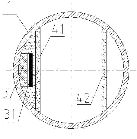
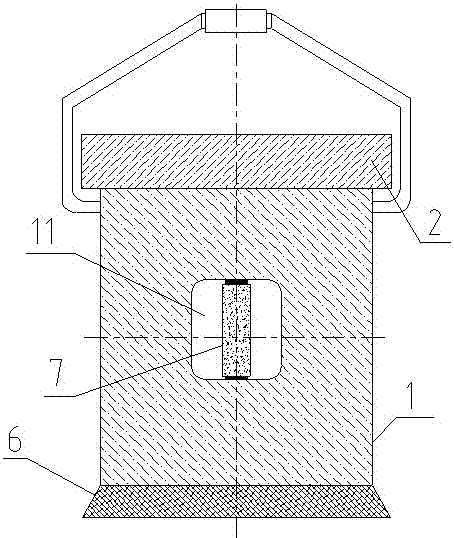
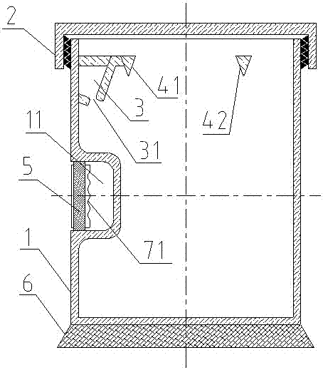
[0019] Such as figure 1 , figure 2 , image 3 As shown, a kind of insulating varnish paint barrel comprises a barrel body 1 and a barrel cover 2, the outer surface of the upper end of the barrel body 1 is provided with threads, and the barrel body 1 and the barrel cover 2 are connected by threads, so The interior of the barrel body 1 is provided with a brush placement groove 3 and a bar 4, the bar 4 includes a left bar 41 and a right bar 42, and the left bar 41 and the right bar 42 are symmetrically arranged on Inside the barrel body 1, its two ends are fixedly connected with the inner surface of the barrel body 1, and the brush placement groove 3 is fixedly arranged between the left retaining bar 41 and the inner surface of the barrel body 1, and the brush Placement groove 3 is not connected between i...


PUM


Abstract

The invention discloses an insulating paint barrel. The insulating paint barrel comprises a barrel body and a barrel cover. A thread is arranged on the outer surface of the upper end of the barrel body. The barrel body and the barrel cover are connected through the thread. A brush containing groove and baffle bars are arranged inside the barrel body. The barrel bars include a left baffle bar and a right baffle bar. The left baffle bar and the right baffle bar are symmetrically arranged inside the barrel body, and the two ends of the left baffle bar and the two ends of the right baffle bar are fixedly connected with the inner surface of the baffle body. The brush containing groove is fixedly formed between the left baffle bar and the inner surface of the barrel body, the side wall of the brush containing groove is not connected with the groove bottom face, and a diversion through groove is formed. A groove is formed in the middle position of the outer surface of the barrel body, a holding rod is arranged in the groove, the two ends of the holding rod are fixedly connected with the upper groove wall and the lower groove wall of the groove correspondingly, and a balance weight platform pad is fixedly arranged at the bottom end of the barrel body. The insulating paint barrel has the beneficial effects of being reasonable in structure and convenient to use.

Description

technical field [0001] The invention belongs to the field of paint storage tools, and in particular relates to an insulating paint bucket. Background technique [0002] Paint buckets are the most common paint storage tools. When people use a brush to dip insulating paint from the paint bucket, they habitually wipe the brush on the edge of the bucket so that the excess insulating paint on the brush falls back into the paint bucket. , to avoid waste and soiling the ground, but after repeated operations, it is easy to cause the insulating paint to drip on the outside of the edge of the paint bucket, dirty fingers, and make it difficult to close the lid and the barrel body, and after the lid is closed It is not easy to separate, which brings great trouble to the workers, and the existing paint bucket is not provided with a brush placement groove, and it is very inconvenient for the workers to place the brush during the rest process; in order to solve the above problems, a A wel...

Claims


Application Information

Patent Timeline
Patent Type & Authority Applications(China)
IPC IPC(8): B65D25/02B65D25/20B65D25/28
CPCB65D25/02B65D25/20B65D25/2805
Inventor 慕洪
Owner HENAN YAAN ELECTRICAL INSULATION MATERIAL PLANT CO LTD
Why Eureka
Try Eureka