
Liquid crystal display device

A technology for liquid crystal display devices and light-shielding parts, which can be used in instruments, nonlinear optics, optics, etc. It can solve problems such as liquid crystal molecular orientation disorder and opening area reduction, and achieve the effect of suppressing the decline in display quality

Active Publication Date: 2020-10-09
JAPAN DISPLAY INC
View PDF10 Cites 0 Cited by
  • Summary
  • Abstract
  • Description
  • Claims
  • Application Information

AI Technical Summary

Problems solved by technology

However, in the vicinity of the columnar spacers, the alignment of the liquid crystal molecules is disordered, so the light-shielding layer is arranged so as to overlap the columnar spacers and their surroundings, resulting in a decrease in the area of ​​the opening.

Method used


Image

  • Liquid crystal display device
  • Liquid crystal display device
  • Liquid crystal display device

Examples


Embodiment Construction

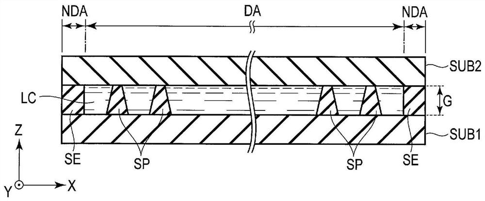
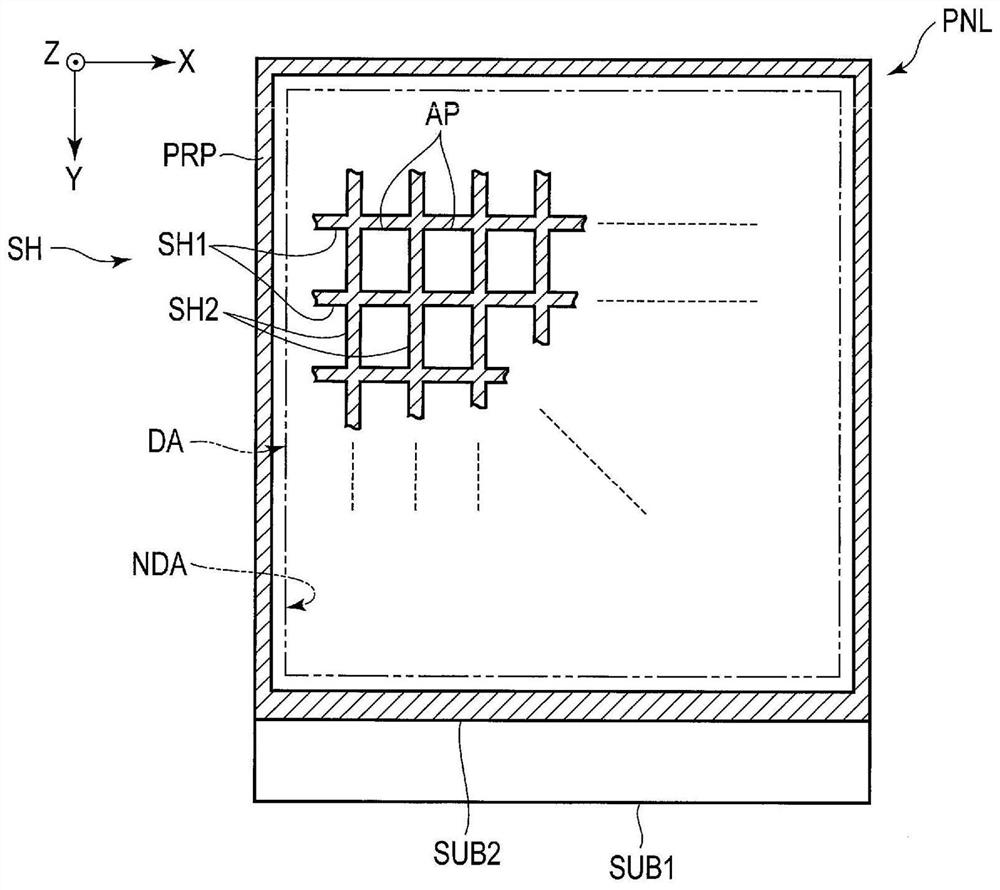
[0032] Hereinafter, this embodiment will be described with reference to the drawings. It should be noted that the present disclosure is merely an example, and appropriate changes that are easily conceivable by those skilled in the art within the scope of the invention are also within the scope of the present invention. In addition, the drawings sometimes schematically show the width, thickness, shape, etc. of each part compared with the actual form for clarity of description, and these are merely examples and do not limitatively explain the present invention. In addition, in this specification and each figure, the same code|symbol is attached|subjected to the component which performs the same or similar function as what was already described in the figure, and the repeated detailed description may be omitted suitably.

[0033] In this embodiment mode, a liquid crystal display device is disclosed as an example of a display device. This display device can be applied to various ...


PUM


Abstract

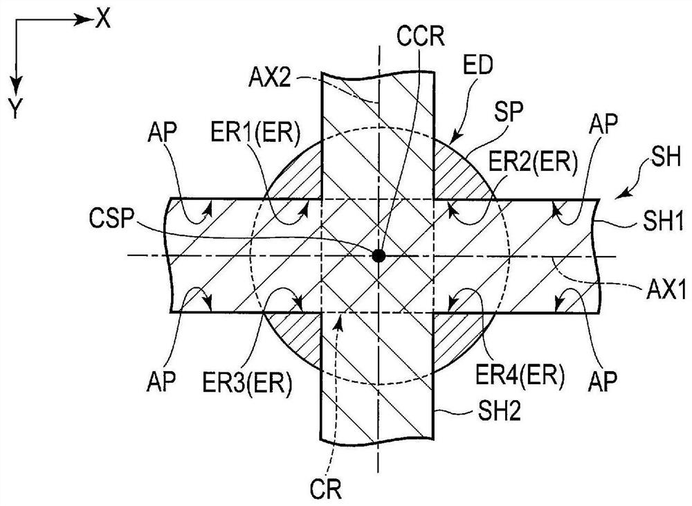
The present invention relates to a liquid crystal display device. According to one embodiment, it includes: a first substrate; a second substrate disposed opposite to the first substrate; a liquid crystal layer disposed between the first substrate and the second substrate; a layer having a first light shielding portion extending in a first direction and a second light shielding portion extending in a second direction and intersecting the first light shielding portion; and a spacer holding the first substrate and the second substrate The gasket has an exposed area that overlaps with the intersecting area where the first light-shielding portion and the second light-shielding portion intersect and is exposed to the outside of the light-shielding layer in plan view.

Description

[0001] Cross-References to Associated Applications [0002] This application is based upon and claims the benefit of priority from Japanese Patent Application No. 2016-048603 filed on March 11, 2016, the entire contents of which are hereby incorporated by reference. technical field [0003] Embodiments of the present invention relate to liquid crystal display devices. Background technique [0004] A liquid crystal display device includes, for example, columnar spacers in order to maintain a gap between a pair of substrates. In order to improve the adhesion to the substrate, the columnar spacer overlaps, for example, the pixel electrode. However, in the vicinity of the columnar spacers, the orientation of the liquid crystal molecules is disordered, so the light-shielding layer is arranged to overlap the columnar spacers and their surroundings, resulting in a decrease in the area of ​​the opening. Contents of the invention [0005] According to this embodiment, a liquid cr...

Claims


Application Information

Patent Timeline
Patent Type & Authority Patents(China)
IPC IPC(8): G02F1/1339G02F1/1335
CPCG02F1/133512G02F1/1339G02F1/13394G02F1/134345G02F1/13398G02F1/133553G02F1/134309G02F1/13439G02F2201/123G02F2201/50
Inventor 玉置昌哉
Owner JAPAN DISPLAY INC
Learn More