Display panel
A display panel and display area technology, applied in the direction of instruments, nonlinear optics, optics, etc., can solve the problem of display quality degradation and achieve the effect of suppressing display quality degradation
- Summary
- Abstract
- Description
- Claims
- Application Information
AI Technical Summary
Problems solved by technology
Method used
Image
Examples
Embodiment approach 1
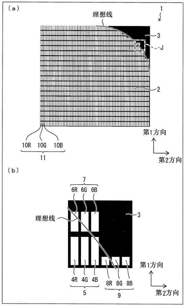
[0056] figure 1 It is a diagram showing the liquid crystal display panel 1 in which the upper right region in the figure is shielded from light by the light shielding portion 3 as part of the edge region in the display region 2 .
[0057] Such as figure 1 As shown in (a), a plurality of pixels 11 are included in the display area 2, and each pixel 11 includes a red sub-pixel 10R that transmits red light at a predetermined transmittance, and a green sub-pixel 10R that transmits green light at a predetermined transmittance. The sub-pixel 10G, and the blue sub-pixel 10B that transmits blue light at a predetermined transmittance. Therefore, in each pixel 11 , a predetermined color can be displayed by appropriately adjusting the transmittance of each color light from the red sub-pixel 10R, the green sub-pixel 10G, and the blue sub-pixel 10B.
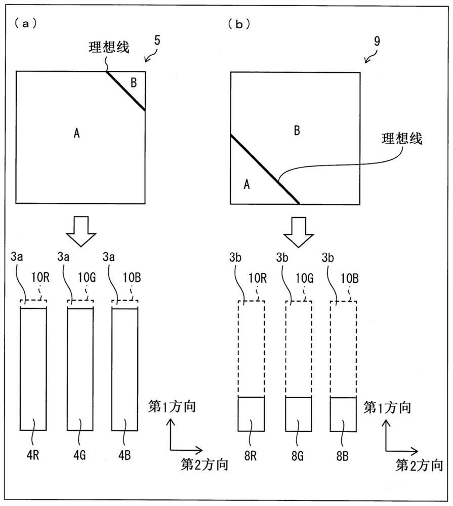
[0058] In this embodiment, the case where one pixel 11 includes three sub-pixels 10R, 10G, and 10B is taken as an example for description...
Embodiment approach 2
[0114] Below, based on Image 6 with Figure 7 Embodiment 2 of the present invention will be described. The difference between the liquid crystal display panel 40 of the present embodiment and the first embodiment is that only the sub-pixels 41R, 41G, 41B, and 43R are adjusted among the pixels 42 , 44 , and 46 passing through the ideal line that is a curved boundary line. , 43G, 43B, 45R, 45G, 45B openings in the second direction perpendicular to the longitudinal direction (first direction), that is, the width of the left-right direction in the figure (the length of the above-mentioned longitudinal direction (first direction) remains is fixed), other content is the same as that described in Embodiment 1. For convenience of description, members having the same functions as those shown in the drawings of Embodiment 1 are assigned the same reference numerals, and description thereof will be omitted.
[0115] Image 6 (a) is a diagram showing the liquid crystal display panel 4...
Embodiment approach 3
[0134] Below, based on Figure 8 with Figure 9 Embodiment 3 of the present invention will be described. The liquid crystal display panel 50 of this embodiment differs from Embodiments 1 and 2 in that the sub-pixel light-shielding portions of the light-shielding portion 3 are set in accordance with the pixel 52 and 54 where an ideal line that is a curved boundary line passes, for example. A grid shape with a plurality of openings is formed, and the size of the openings of the sub-pixels 51R, 51G, 51B, 53R, 53G, and 53B, that is, the size of the sub-pixel light-shielding portion of the light-shielding portion 3 is adjusted by changing the density of the openings, Other contents are the same as those described in Embodiments 1 and 2. For convenience of description, members having the same functions as those shown in the drawings of Embodiments 1 and 2 are assigned the same reference numerals, and description thereof will be omitted.
[0135] Figure 8 (a) is a diagram showin...
PUM
 Abstract
Description
Claims
Application Information
 - R&D
- Intellectual Property
- Life Sciences
- Materials
- Tech Scout
- Unparalleled Data Quality
- Higher Quality Content
- 60% Fewer Hallucinations
Browse by: Latest US Patents, China's latest patents, Technical Efficacy Thesaurus, Application Domain, Technology Topic, Popular Technical Reports.
© 2025 PatSnap. All rights reserved.Legal|Privacy policy|Modern Slavery Act Transparency Statement|Sitemap|About US| Contact US: help@patsnap.com


