Double-mode valve device and fluid supply system thereof

A valve device, valve device technology, applied in valve device, multi-port valve, engine components and other directions, can solve the problem of rough control of water temperature and other issues

Pending Publication Date: 2017-09-22
CHENGDU JINGYI TECH CO LTD
View PDF8 Cites 0 Cited by
  • Summary
  • Abstract
  • Description
  • Claims
  • Application Information

AI Technical Summary

Problems solved by technology

Under the existing technology, users can only frequently adjust the hot fluid supply temperature repeatedly in the hot fluid supply device (such as a water heater), or roughly control the outlet water temperature by roughly adjusting the mixing ratio of cold water and hot water on the valve.

Method used


Image

  • Double-mode valve device and fluid supply system thereof
  • Double-mode valve device and fluid supply system thereof
  • Double-mode valve device and fluid supply system thereof

Examples


Embodiment 1

[0094] A valve device, comprising a valve device for controlling a fluid passing state when the fluid passes through, and an operating mechanism for realizing the aforementioned control by operating in its operating region, the valve device has a first fluid inlet port, a second fluid inlet port and a fluid At the outlet end, the operation area of ​​the operating mechanism is divided into a mixing degree adjustment area for adjusting the mixing degree of the first fluid and the second fluid, and a flow adjustment area for adjusting the flow rate of the fluid outlet in the mixing degree adjustment area. The mixing degree adjustment area includes necessary The fluid outlet port exits only the first fluid region of the first fluid, and the fluid outlet port exits only the second fluid region of the second fluid, and there may be a fluid outlet port exiting the mixing region of the mixed fluid of the first fluid and the second fluid The flow rate of the operating mechanism at the m...

Embodiment 2

[0101] This embodiment is similar to Embodiment 1, the difference is that in this embodiment, the water-saving valve core is in the critical state of Mode A when the control handle is placed in the lower stop position of Mode A, and when the control handle is placed in the lower stop position of Mode B The water spool is in the closed state, from the lower stop of mode A to the upper stop of mode A is the large flow adjustment area of ​​the water-saving spool A mode, and from the lower stop of mode A to the lower stop of mode B is the water-saving spool A mode Small flow regulation area.

[0102] In this embodiment, the flow rate in the critical state of mode A of the water-saving valve core is set to 5 liters / minute. In this way, the adjustment area of ​​the water-saving valve core A mode is divided into a large flow adjustment area and a small flow adjustment area, that is, from the lower stop position of the A mode to the upper stop position of the A mode, the water-saving ...

Embodiment 3

[0105] Such as Figure 1 to Figure 6 As shown, this embodiment is basically the same as Embodiment 1. More specifically, this embodiment is a ceramic disc single-handle dual-mode water-saving valve core. The control handle has an upper stop, an adjustment area and a lower stop. The core state has an on state and an off state. In this embodiment, the water-saving valve core is provided with a mode and a mode B. The maximum flow rate in the adjustment area of ​​the A mode is 20 liters / minute, and the maximum flow rate in the adjustment area of ​​the B mode is 5 liters / min.

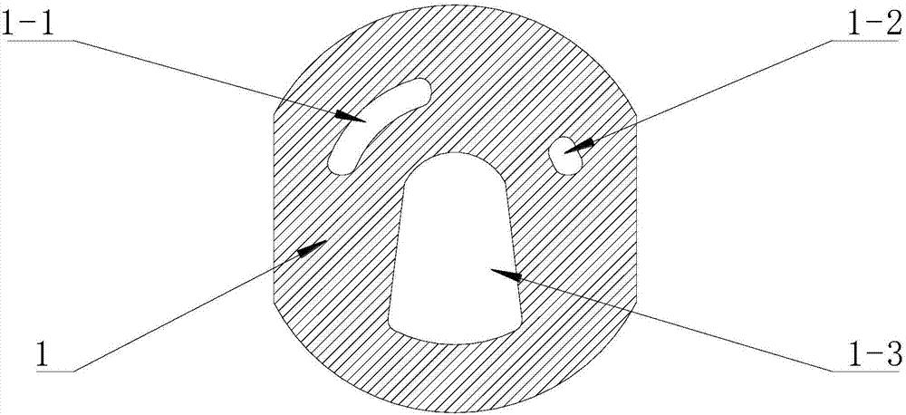
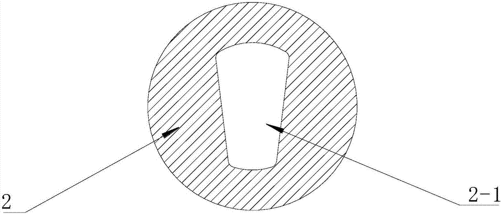
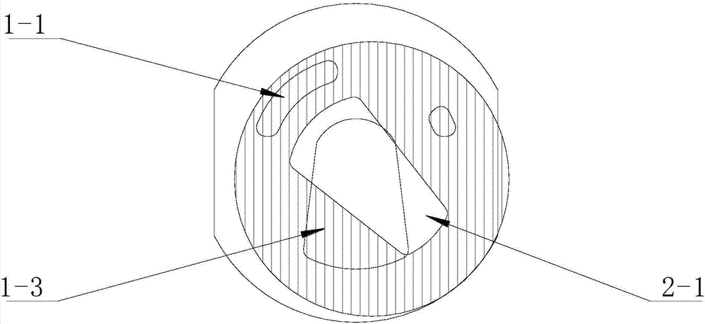
[0106] figure 1 Be fixed plate 1 sectional schematic diagram, (among the figure) top left side is first water inlet 1-1, top right side is second water inlet 1-2, and bottom is water outlet 1-3. figure 2 It is a schematic cross-sectional view of the moving piece 2, and the middle part (in the figure) is the channel 2-1. The single-handle double-mode water-saving valve core of the present embodiment is co...


PUM


Abstract

The invention discloses a valve device and a fluid supply system thereof. The valve device comprises a valve unit controlling the passing state of fluid during passing, and an operation mechanism operating in an operation area of the operation mechanism to achieving the control. The valve unit is provided with a first fluid inlet end, a second fluid inlet end and a fluid outlet end. The operation area of the operation mechanism is divided into a mixing degree adjusting area adjusting the mixing degree of first fluid and second fluid, and a flow adjusting area adjusting the flow of the fluid outlet end in the mixing degree adjusting area. The mixing degree adjusting area comprises a necessary first fluid area with a fluid outlet end through which only the first fluid flows out, a necessary second fluid area with a fluid outlet end through which only the second fluid flows out, and a dispensable mixing area with a fluid outlet end through which mixed fluid of the first fluid and the second fluid flow out. The flow of the operation mechanism in the maximum stop position of the flow adjusting area of the first flow area and the flow of the maximum stop position of the flow adjusting area of the second flow area are unequal. Through the valve device and the fluid supply system thereof, the fluid flowing through the valve device can be saved, and normal use of a hot fluid supply device can be facilitated.

Description

technical field [0001] The invention belongs to the field of valves, in particular to the technical field of valve cores used in faucets, in particular to a single-handle dual-mode water-saving valve core. Background technique [0002] As one of the most commonly used control devices in production and life, valves are used to control the state of fluid passage, such as controlling the type of fluid passing through and controlling the flow of fluid passing through. Ordinary people know and contact the most is the faucet used in daily life. According to the opening method, the faucet can usually be divided into screw type, wrench type, lifting type and induction type. The screw-type handle is opened by screwing, and when it is opened, it needs to be rotated many times to adjust the water flow through the number of turns, the more the number of turns, the greater the flow; The larger the opening angle, the greater the flow. The maximum angle is usually 90°; the lifting handle...

Claims


Application Information

Patent Timeline
IPC IPC(8): F16K11/074
CPCF16K11/074
Inventor 姚明行苏强
Owner CHENGDU JINGYI TECH CO LTD
Why Eureka
Try Eureka