

Method for controlling screwing spindle
A control method, piston technology, applied in the direction of bottle filling, packaging, screw caps, etc., can solve the problem of damage to the cap or the neck of the package
- Summary
- Abstract
- Description
- Claims
- Application Information
AI Technical Summary
Problems solved by technology
Method used
Image

Examples
Embodiment Construction
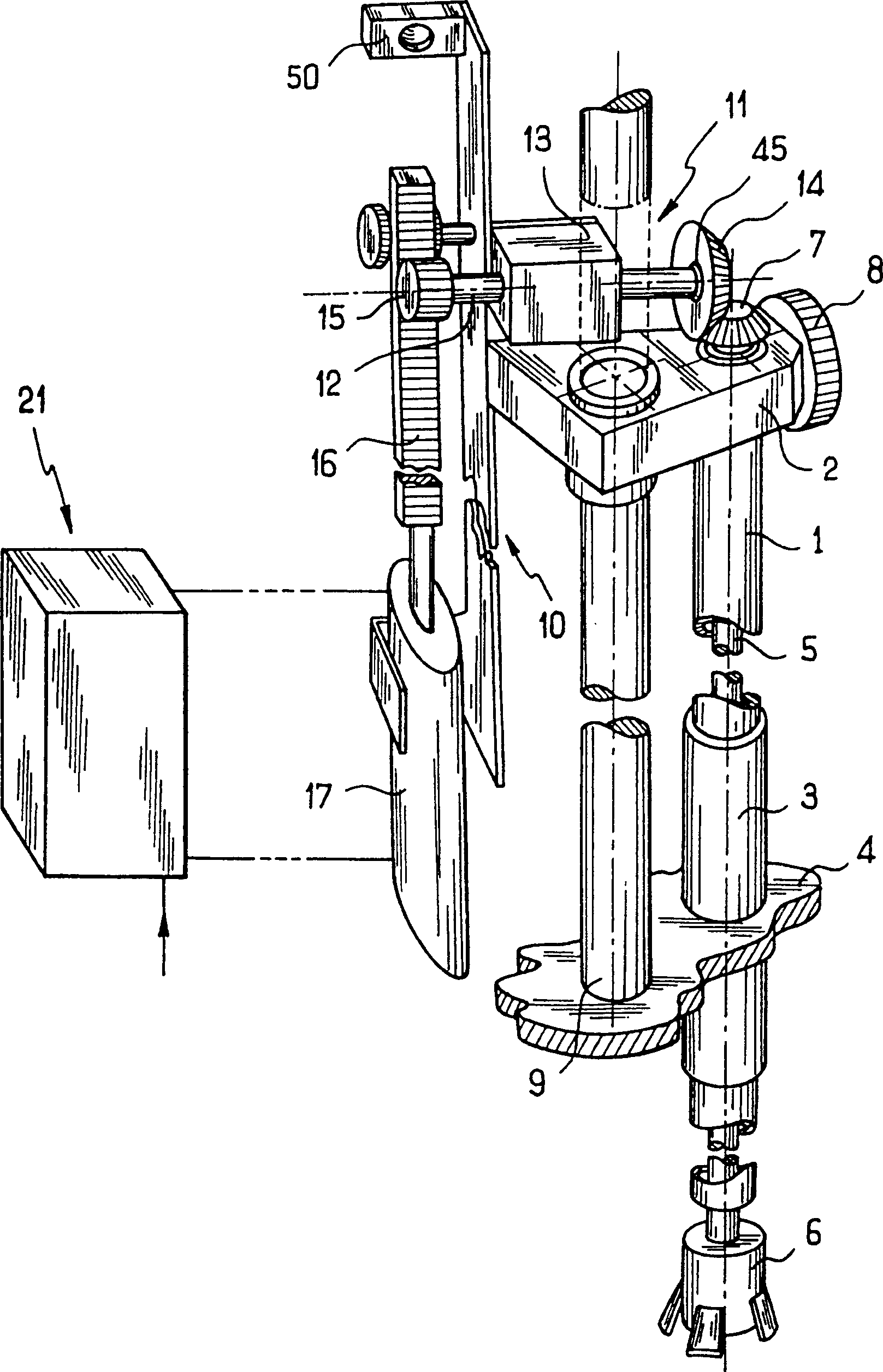
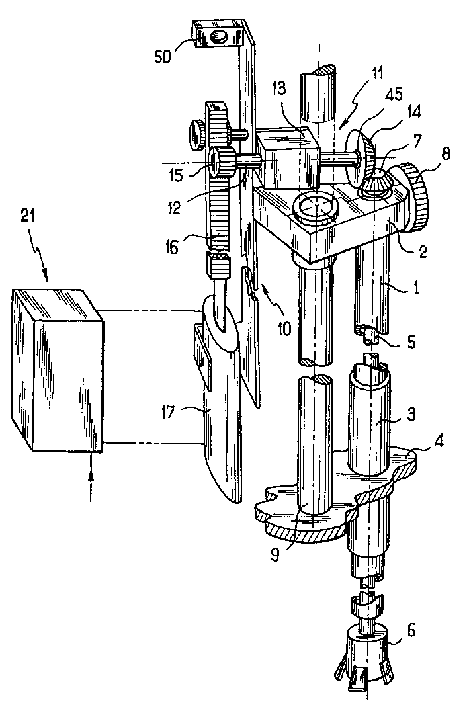
[0019] Referring to the drawings, the screwdriver controlled by the method of the present invention is conventional in structure and operation, some of its components not shown in the figures. In the embodiment shown, the shaft comprises a vertical guide tube 1 housed in a shaft support 2 and slidable vertically in a bushing 3 fixed to a rotating platform 4 . The guide tube 1 rotatably receives a mandrel 5, the bottom end of which protrudes outside the guide tube 1, and has a jaw chuck device 6 on which the cover is placed. The top of mandrel 5 has a bevel gear 7, and this gear and reference figure 1 Cooperate with the drive components shown in the overall above.
[0020] The shaft support 2 is mounted so as to slide on a column 9 fixed to the rotating platform 4, the support has a wheel 8 designed to cooperate with a cam of a stationary structure for positioning the support 2 and in the vertical direction. Fits with its associated parts in the vertical direction.
[0021] ...
PUM
 Abstract
Description
Claims
Application Information