Single side constant flow valve device and its fluid supply system

A valve device, valve device technology, applied in valve device, valve operation/release device, valve heating/cooling device, etc., can solve problems such as rough control of outlet water temperature

Active Publication Date: 2019-04-12
安徽领克自控设备有限公司
View PDF8 Cites 0 Cited by
  • Summary
  • Abstract
  • Description
  • Claims
  • Application Information

AI Technical Summary

Problems solved by technology

Under the existing technology, users can only frequently adjust the hot fluid supply temperature repeatedly in the hot fluid supply device (such as a water heater), or roughly control the outlet water temperature by roughly adjusting the mixing ratio of cold water and hot water on the valve.

Method used


Image

  • Single side constant flow valve device and its fluid supply system
  • Single side constant flow valve device and its fluid supply system
  • Single side constant flow valve device and its fluid supply system

Examples


Embodiment 1

[0084] A valve device, comprising a valve device for controlling a fluid passing state when the fluid passes through, and an operating mechanism for realizing the aforementioned control by operating in its operating region, the valve device has a first fluid inlet port, a second fluid inlet port and a fluid At the outlet end, the operation area of ​​the operating mechanism is divided into a mixing degree adjustment area for adjusting the mixing degree of the first fluid and the second fluid, and a flow adjustment area for adjusting the flow rate of the fluid outlet in the mixing degree adjustment area. The mixing degree adjustment area includes necessary The fluid outlet port exits only the first fluid region of the first fluid, and the fluid outlet port exits only the second fluid region of the second fluid, and there may be a fluid outlet port exiting the mixing region of the mixed fluid of the first fluid and the second fluid The flow rate of the operating mechanism at the m...

Embodiment 2

[0092] This embodiment is similar to Embodiment 1, except that in this embodiment, the critical state is set to the stop position in the heat-only mode, and the stop position in the cooling-only mode is the closed state of the spool.

[0093]The valve device of this embodiment, and the thermal fluid supply device (such as various water heaters) etc. which have a heating system for heating the fluid in it constitute a thermal fluid supply system, the thermal fluid outlet of the thermal fluid supply device and the first valve device A fluid inlet port (hot fluid inlet port, such as a hot water inlet hole) is connected, and is controlled by the operating mechanism of the valve device (including direct control or indirect control). The hot fluid supply device turns on or off its hot fluid supply, and the hot fluid supply device There is a minimum flow rate to close its heating system. When the flow rate of the first fluid inlet port (hot fluid inlet port, such as a hot water inlet ...

Embodiment 3

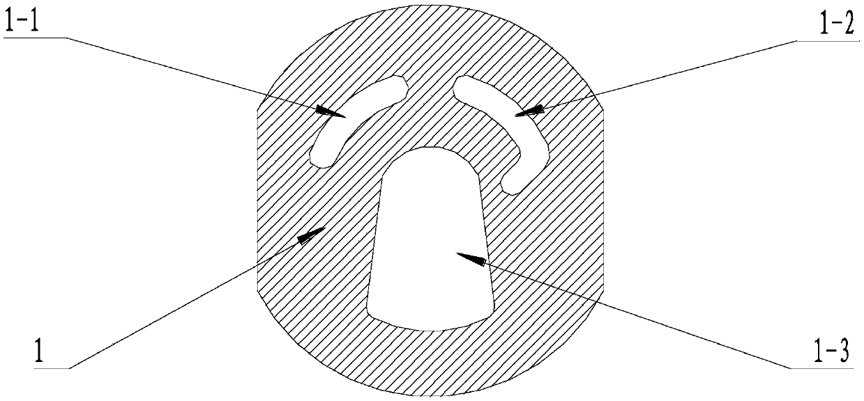
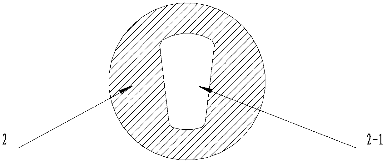
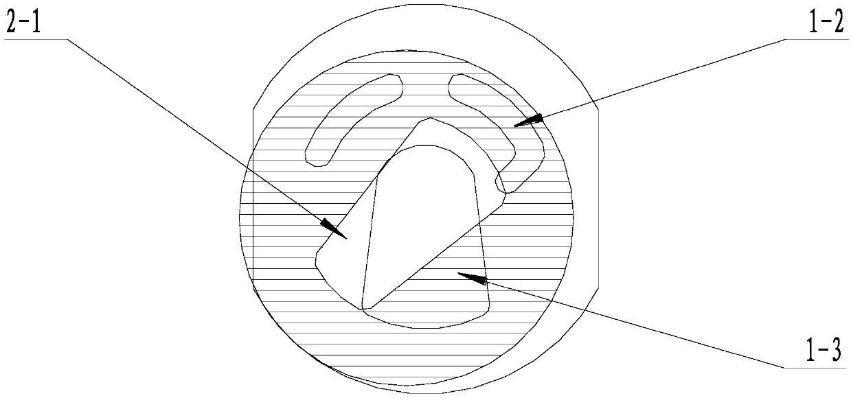
[0096] Such as Figure 1 to Figure 6 As shown, this embodiment is basically the same as Embodiment 1, more specifically, it is a ceramic single-handle double-connected water-saving valve core, the valve core mode has a single-heating mode and a single-cooling mode, and the control handle has an upper stop position , adjustment area and bottom stop position, the state of the spool has an open state and a closed state, when the control handle is placed at the bottom stop position of the single heat mode, the water-saving valve core is in the critical state of the single heat mode, and the control handle is placed in the only cooling mode The water-saving spool is in the closed state when it is in the stop position. From the bottom stop in the heat-only mode to the top stop in the heat-only mode is the large flow adjustment area of ​​the water-saving spool in the heat-only mode. From the bottom stop in the heat-only mode to the cooling-only mode The stop position is the small flo...


PUM


Abstract

A valve device and a fluid supplying system thereof. The valve device is provided with a first fluid inlet end (1-2), a second fluid inlet end (1-1) and a fluid outlet end (1-3); an operating area of an operating mechanism is divided into a mixing degree adjusting area for adjusting the mixing degree of a first fluid and a second fluid and a flow adjusting area that is always capable of adjusting the flow of the fluid outlet end (1-3) of the valve device in the whole mixing degree adjusting area; the mixing degree adjusting area is divided into a first fluid area in which the first fluid is only drained from the fluid outlet end (1-3), a mixing area in which a mixed fluid of the first fluid and the second fluid is drained from the fluid outlet end (1-3) and a second fluid area in which the second fluid is only drained from the fluid outlet end (1-3); and the flow of the operating mechanism at a minimum stop position in the flow adjusting area of the first fluid area is greater than zero, and the flow of the operating mechanism at a minimum stop position in the flow adjusting area of the second fluid area is equal to zero. The valve device and the thermal fluid supplying system thereof facilitate the conservation of fluid passing through the valve device, and facilitate normal use of a thermal fluid supplying device.

Description

technical field [0001] The invention belongs to the field of valves, in particular to the technical field of valve cores used in faucets, in particular to a single-handle double-connected water-saving valve core. Background technique [0002] As one of the most commonly used control devices in production and life, valves are used to control the state of fluid passage, such as controlling the type of fluid passing through and controlling the flow of fluid passing through. Ordinary people know and contact the most is the faucet used in daily life. According to the opening method, the faucet can usually be divided into screw type, wrench type, lifting type and induction type. The screw-type handle is opened by screwing, and when it is opened, it needs to be rotated many times to adjust the water flow through the number of turns, the more the number of turns, the greater the flow; The larger the opening angle, the greater the flow. The maximum angle is usually 90°; the lifting...

Claims


Application Information

Patent Timeline
Patent Type & Authority Patents(China)
IPC IPC(8): F16K11/074F16K3/314F16K31/60F16K49/00
CPCF16K11/074F16K11/22
Inventor 姚明行
Owner 安徽领克自控设备有限公司
Why Eureka
Try Eureka