Power supply device and vehicle provided with power supply device

A power supply device, battery technology, applied in battery/battery traction, battery/fuel cell control device, electric vehicle, etc.

Active Publication Date: 2017-09-26
SANYO ELECTRIC CO LTD
View PDF4 Cites 6 Cited by
  • Summary
  • Abstract
  • Description
  • Claims
  • Application Information

AI Technical Summary

Problems solved by technology

[0008] The present invention is made to solve the conventional problems

Method used


Image

  • Power supply device and vehicle provided with power supply device
  • Power supply device and vehicle provided with power supply device
  • Power supply device and vehicle provided with power supply device

Examples


Embodiment Construction

[0039] The power supply device of the present invention can be applied to a power supply that is mounted on an electric vehicle such as a hybrid car or an electric vehicle and supplies electric power to a running motor, a power supply for storing power generated by natural energy such as solar power generation or wind power generation, or a power supply for storing It can be used in various applications such as a power supply for late-night power, and can be used especially as a power supply suitable for applications with high power and high current.

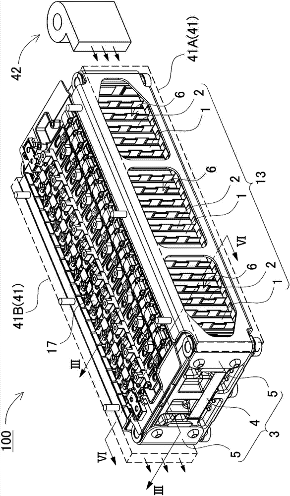
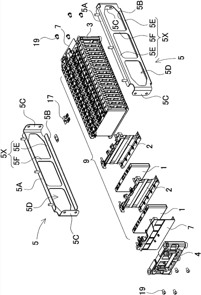
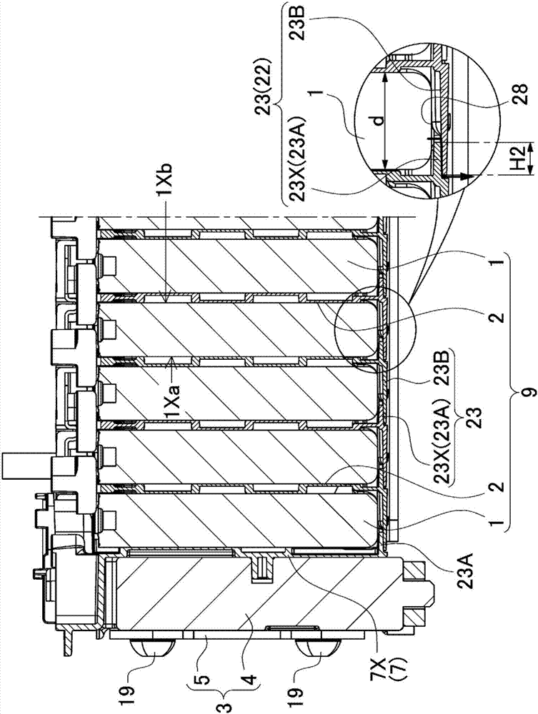
[0040] figure 1 A power supply device 100 according to one embodiment of the present invention is shown. Figure 1 to Figure 8The power supply device 100 shown has: a plurality of battery cells 1 formed in a square shape; a separator 2 interposed between the battery cells 1 in a state in which the plurality of battery cells 1 are stacked; The fixing member 3 is used to fasten the battery stack 9 formed by stacking a plurality ...


PUM


Abstract

In order to simplify a structure for insulating battery cells from each other while maintaining the creeping distance between a battery cell and a fastening member and thereby make it possible to effectively prevent shorts through condensation water and the like, a power supply device is provided with: a plurality of battery cells (1) having a rectangular external shape; separators interposed between battery cells (1) while the plurality of battery cells (1) are in a stacked state in order to insulate battery cells (1) that are adjacent to each other; and a fastening member for fastening a battery stack in which the battery cells (1) and the separators are stacked in an alternating manner. The separators are provided with a clamping plate section (20) that is arranged between the facing main surfaces of adjacent battery cells (1). A plate-like bottom surface covering section (23) that protrudes in the stacking direction of the battery cells (1) and that covers the bottom surfaces of the battery cells (1) is provided to both surfaces of the clamping plate section (20) on the lower end of the clamping plate section (20). The bottom surface covering sections (23) of the separators stacked on both surfaces of the battery cells (1) in the power supply device are stacked together on the bottom surfaces of the battery cells (1).

Description

technical field [0001] The present invention relates to a power supply device for large current used as a power supply for driving a motor of a vehicle such as a hybrid vehicle or an electric vehicle, and a vehicle including the power supply device. Background technique [0002] A power supply device in which a plurality of battery cells with a rectangular outer can is stacked is used in vehicle applications and the like. In such a battery cell, since the positive and negative electrode plates and the electrolytic solution are filled in the conductive outer can, the outer can has potential. Therefore, it is necessary to insulate adjacent exterior cans of stacked battery cells from each other. As such an insulating structure, for example, it has been proposed to cover the surface of the battery cell with a shrink tube made of resin (for example, Patent Document 1), or to accommodate the battery cell in a case made of resin, or to insulate the inside of the outer can to make ...

Claims


Application Information

Patent Timeline
Patent Type & Authority Applications(China)
IPC IPC(8): H01M2/10H01M2/34H01M10/613H01M10/625H01M10/647H01M10/6557H01M10/6563H01M50/209H01M50/264H01M50/293H01M50/588H01M50/593
CPCH01M10/625H01M10/6563H01M10/647H01M10/6557H01M10/613H01M10/0486H01M10/643B60L58/26B60L50/66B60L50/64Y02T10/70Y02E60/10H01M50/256H01M50/576Y02P70/50H01M50/293H01M50/588H01M50/209H01M50/264H01M50/593H01M50/24H01M10/0481H01M2220/20
Inventor 冈田渉植田義明菅原秀一盐津吉洋
Owner SANYO ELECTRIC CO LTD
Why Eureka
Try Eureka