Electric dust collecting unit

An electrostatic dust collection and dust collection technology, applied in electrode structure, electrostatic separation, external electrostatic separator, etc., can solve the problems of insufficient dust collection performance, unsuitable for the thinning of electrostatic dust collection units, etc., and improve deodorization efficiency. , to achieve the effect of thinning and improving dust collection performance

Inactive Publication Date: 2011-01-19
PANASONIC CORP
View PDF7 Cites 1 Cited by
  • Summary
  • Abstract
  • Description
  • Claims
  • Application Information

AI Technical Summary

Problems solved by technology

In such a conventional electric dust collection unit, the tip of the needle-shaped discharge electrode 104 is oriented in a direction substantially parallel to the ground electrode 105, and the dust collection performance is insufficient. Moreover, this structure is not suitable for the thin electric dust collection unit. change

Method used


Image

  • Electric dust collecting unit
  • Electric dust collecting unit
  • Electric dust collecting unit

Examples


Embodiment approach 1

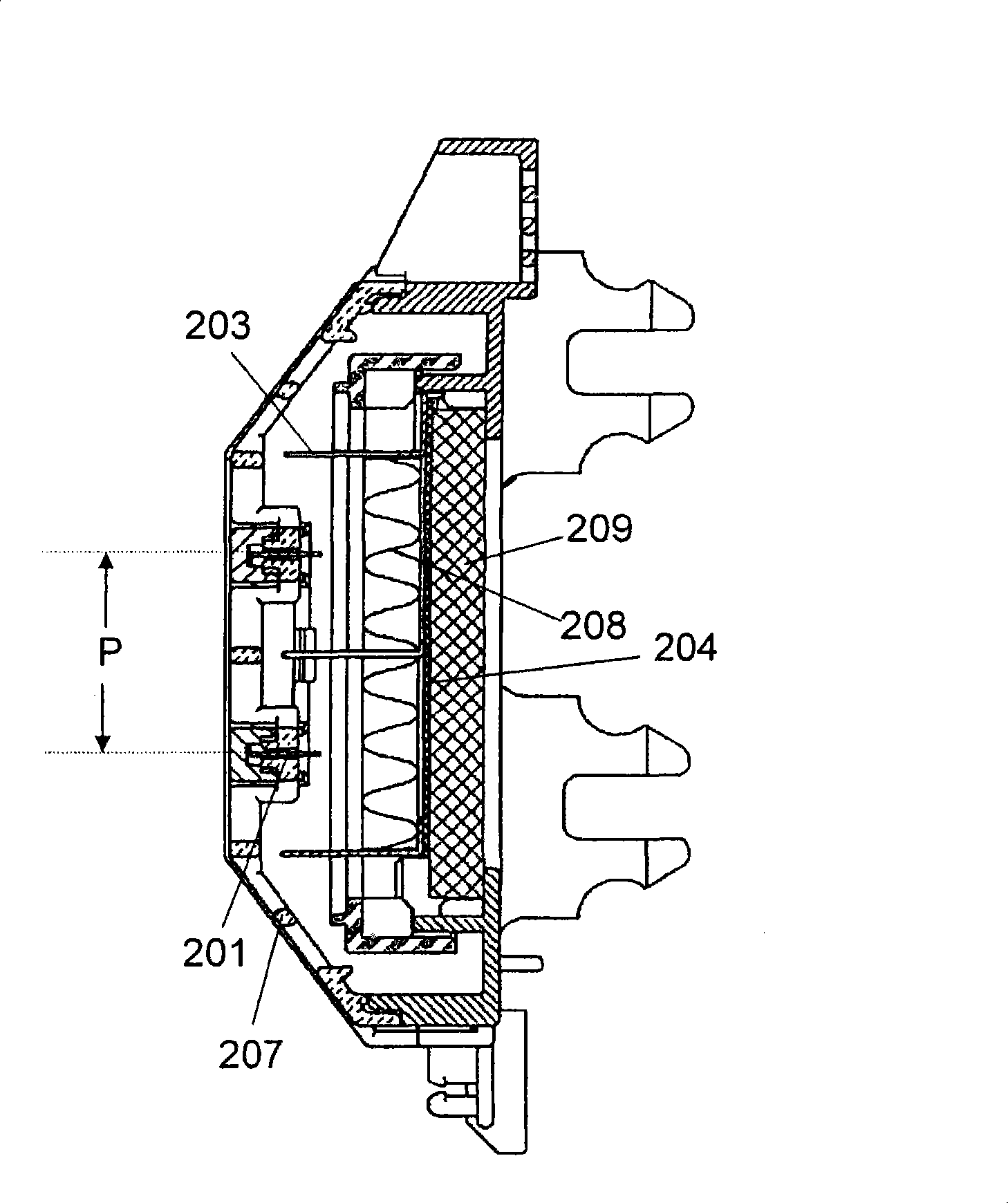
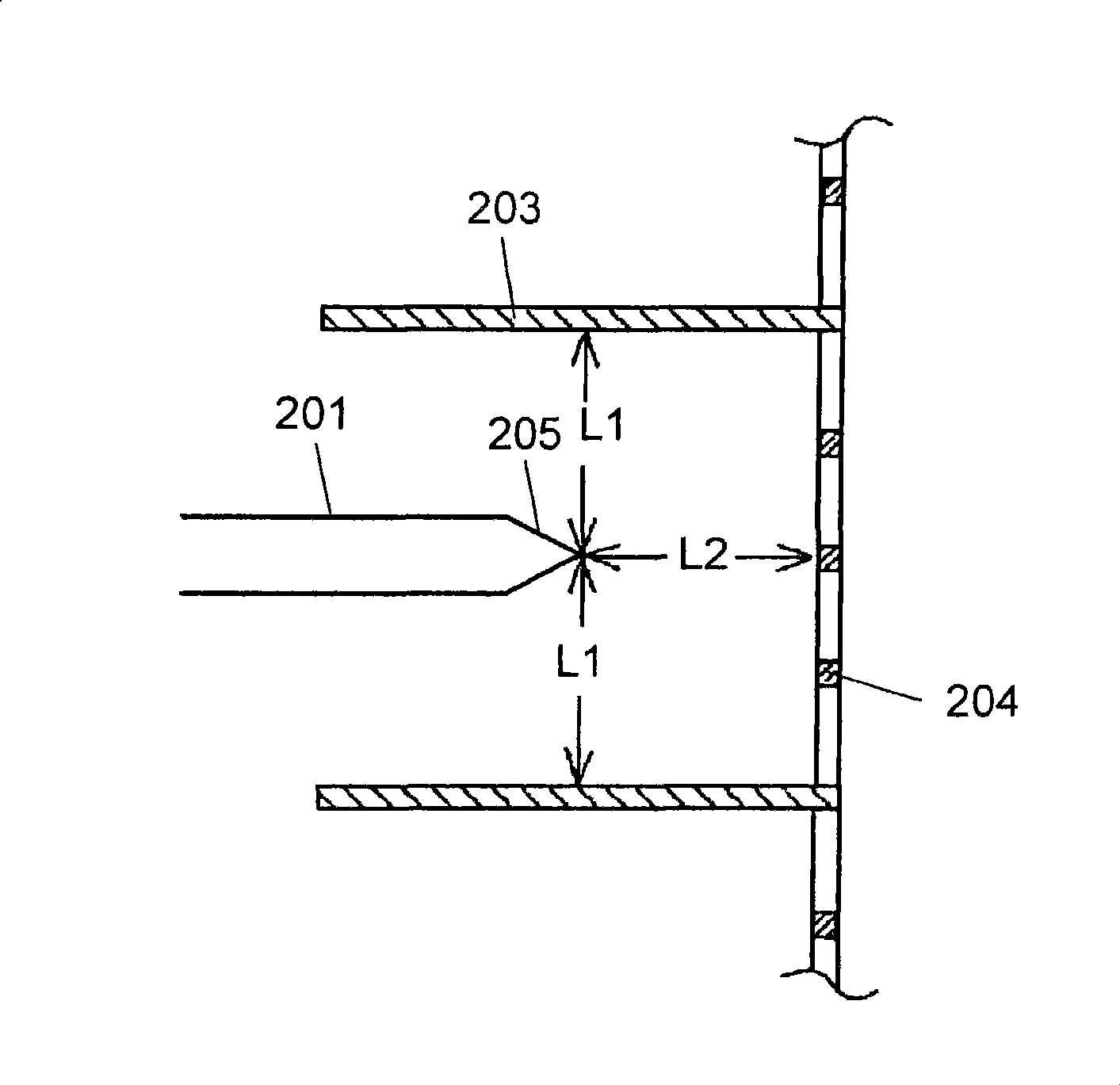
[0127] Figure 1 to Figure 7 Shown is the electric dust collecting unit related to Embodiment 1 of the present invention. Such as Figure 1 to Figure 7 As shown, the electric dust collecting unit of the present invention has a plurality of needle-shaped electrodes 201 and needle-shaped electrode plates 202 arranged in parallel and at equal intervals. Further, there are plate-shaped parallel electrodes 203 parallel to the needle-shaped electrode plate 202 and arranged at equal intervals; and plate-shaped apertured electrodes 204 supporting the parallel electrodes 203 ; Further, facing the tip portion 205 of the acicular electrode 201 , the apertured electrode 204 is provided on the downstream side, and the parallel electrode 203 and the apertured electrode 204 are arranged in a nearly U-shape so as to surround the acicular electrode 201 .

[0128] In addition, "U" itself has a straight line part and a curved line part. However, the "U-shape" described in the present inventio...

Embodiment approach 2

[0141] Figure 8A , Figure 8B The electrode of the electric dust collection unit related to Embodiment 2 is shown. Such as Figure 8A , Figure 8B As shown, a dust collecting filter 208A or a deodorizing filter 209A is provided on the downstream side in contact with the apertured electrode 204A.

[0142] Such as Figure 8A As shown, when dust collection filter 208A is provided in contact with the downstream side of aperture electrode 204A, charged dust can be collected by discharging from tip 205 of needle electrode 201 to which a high voltage is applied.

[0143] Such as Figure 8B As shown, in the case where the deodorizing filter 209A is provided in contact with the downstream side of the apertured electrode 204A, it is possible to collect charged dust while discharging from the tip 205 of the needle-shaped electrode 201 to which a high voltage is applied. Captures odorous components and improves dust collection efficiency while exerting the deodorizing function.

Embodiment approach 3

[0145] Figure 9A , Figure 9BThe electrode of the electric dust collection unit which concerns on Embodiment 3 is shown. Such as Figure 9A , Figure 9B As shown, the dust collecting filter 208B or the deodorizing filter 209B provided on the downstream side of the apertured electrode 204B is configured to have conductivity.

[0146] exist Figure 9A Among them, in the case where the conductive dust collection filter 208B is provided in contact with the aperture electrode 204B, the entire surface of the dust collection filter 208B can be brought to the ground potential. As a result, charged dust is collected by the dust filter 208B by discharging from the tip portion 205 of the needle electrode 201 to which a high voltage is applied, and the dust collection efficiency is improved.

[0147] exist Figure 9B In the middle, a conductive deodorizing filter 209B is provided in contact with the apertured electrode 204B. In such a case, the entire surface of the deodorizing fi...


PUM


Abstract

An electric dust-collecting unit having improved dust collecting performance and thinned. The electric dust-collecting unit has needle-like electrodes (201) each having a sharp tip section (205) in the downstream direction, parallel electrodes (203) arranged in parallel to the needle-like electrodes (201), and open electrodes (204) provided on the downstream side, facing the sharp tip sections (205) of the needle-like electrodes (201). The parallel electrodes (203) and the open electrodes (204) are disposed in a substantially U shape so as to surround the needle-like electrodes (201). Discharge from the needle-like electrodes (201) to the opposite electrodes is made in many directions, which improves dust-collecting performance. Further, the needle-like electrodes (201) can be placed close to the open electrodes (204), so that the electric dust-collecting unit can be thinned.

Description

technical field [0001] The present invention relates to an electric dust collector installed in an air flow path of an air conditioner or the like to remove dust and the like contained in the conditioned air. Background technique [0002] In the prior art, it is well known that needle-shaped discharge electrodes are provided in the existing electric precipitating unit (for example, Japanese Patent Publication, Unexamined Patent Publication No. 2003-10731, refer to figure 1 ). [0003] Below, refer to Figure 31 This electric dust collecting unit will be described. [0004] Such as Figure 31 As shown, a needle-shaped discharge electrode 104 is provided on the suction port 101 side of the filter frame 103 in which the suction port 101 and the blowing port 102 are formed. Opposite to the discharge electrode 104, an air-permeable ground electrode 105 such as lath or punching metal is provided in the air outlet 102 of the filter frame 103. A filter 106 is provided on the wi...

Claims


Application Information

Patent Timeline
Patent Type & Authority Patents(China)
IPC IPC(8): B03C3/02B03C3/41A61L9/16B03C3/47
Inventor 甲斐彻岩桥弘
Owner PANASONIC CORP
Why Eureka
Try Eureka