Self-balanced anti-fatigue testing platform of large-size cantilever type bearing structure

A load-bearing structure and self-balancing technology, which is applied in the field of anti-fatigue experiments, can solve problems such as poor load conditions in the foundation area, easy damage to the foundation, and large local loads at the anchorage point at the fixed end, so as to achieve a firm structure of the tooling body and avoid fatigue The effect of loading

Active Publication Date: 2017-10-17
CHANGAN UNIV
View PDF6 Cites 0 Cited by
  • Summary
  • Abstract
  • Description
  • Claims
  • Application Information

AI Technical Summary

Problems solved by technology

Generally, when carrying out fatigue tests on large-scale cantilever samples, bolts are usually used to directly anchor the fixed end of the sample on the steel cover plate foundation. When the cantilever end bears fatigue load, due to the influence of the length of the cantilever arm, the local The load is large. Under the long-term fatigue test load, the load condition of the foundation area connected to the specimen is harsh, and the foundation is easily damaged, which in turn affects the test results.

Method used


Image

  • Self-balanced anti-fatigue testing platform of large-size cantilever type bearing structure
  • Self-balanced anti-fatigue testing platform of large-size cantilever type bearing structure
  • Self-balanced anti-fatigue testing platform of large-size cantilever type bearing structure

Examples


Embodiment Construction

[0032] The present invention will be described in further detail below in conjunction with the accompanying drawings.

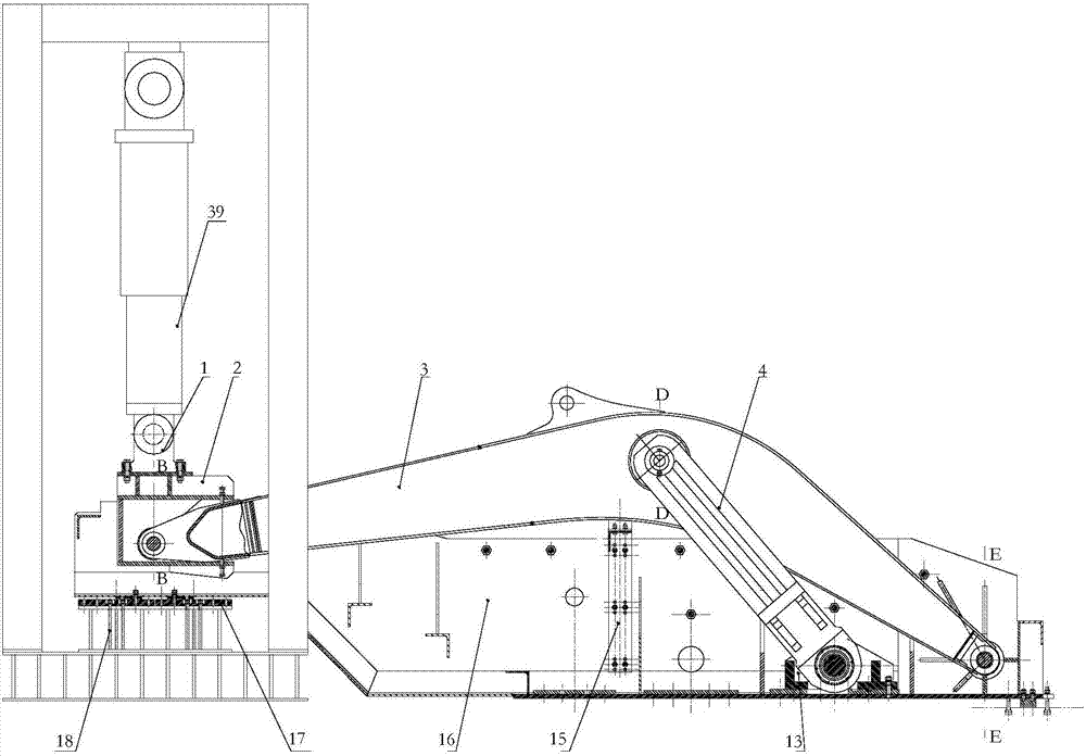
[0033] In the following, the end where the actuator 39 is located is taken as the left, and the actuator 39 is located above the force applying frame 2, which is only for describing the present invention more clearly, rather than limiting the present invention.

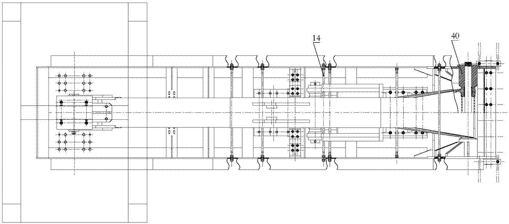
[0034] Such as Figure 1 to Figure 2 As shown, the present invention comprises a bearing frame, a tooling body 16 installed on the carrier frame, a test piece 3, and a force-applying frame 2. The carrier frame is connected with the beam below the column of the fatigue testing machine by bolts, and the left end of the tooling body 16 passes through the first A screw is fixed on the bearing frame, and the right end of the tooling body 16 is fastened to the T-shaped groove on the foundation by bolts. The test piece 3 is a cantilever structure fatigue test piece, and the right end of the test piece 3 is ...


PUM


Abstract

The invention relates to a self-balanced anti-fatigue testing platform of a large-size cantilever type bearing structure. The self-balanced anti-fatigue testing platform comprises a bearing rack and a tooling body, wherein the bearing rack is connected with a fatigue testing machine; a fixed end of a test part is mounted on the tooling body; the left end of the tooling body is mounted on the bearing rack; the right end of the tooling body is fixed on a foundation; a stressing frame on which the cantilever end of the test part is mounted is mounted at the left end of the tooling body; the stressing frame is positioned under an actuator; the stressing frame is hinged with the actuator via a linking hinge; the hinging center of the stressing frame and the actuator and the connecting center of the tooling body and the bearing rack are both at the oil cylinder axis of the actuator. As the hinging center of the platform and the connecting center of the tooling body and the bearing rack are in collineation along the oil cylinder axis of the actuator, the overall structure of the bearing rack is prevented from an additional bending moment of the load of the vertical actuator, the right end of the tooling body and the fixing end of the foundation are not affected by a vertical fatigue load when a fatigue load is exerted, and thus the safety of the foundation below the test part is protected.

Description

technical field [0001] The invention belongs to the technical field of anti-fatigue experiments, in particular to a self-balancing anti-fatigue test bench of a large cantilever bearing structure. Background technique [0002] Large cantilever structural parts will bear bending fatigue loads during work, and fatigue failures are prone to occur at stress concentration or welding positions in the tensile stress area, so fatigue tests are required before the new structure is finalized. Generally, when carrying out fatigue tests on large-scale cantilever samples, bolts are usually used to directly anchor the fixed end of the sample on the steel cover plate foundation. When the cantilever end bears fatigue load, due to the influence of the length of the cantilever arm, the local The load is large. Under the long-term fatigue test load, the load condition of the foundation area connected to the specimen is harsh, and the foundation is easily damaged, which in turn affects the test ...

Claims


Application Information

Patent Timeline
IPC IPC(8): G01N3/36
Inventor 王斌华邵雨虹罗佳佳吕彭民郁录平
Owner CHANGAN UNIV
Why Eureka
Try Eureka