Clapboard frame structure of automobile body
A frame structure and partition technology, which is applied to the substructure, vehicle parts, transportation and packaging, etc., can solve the problems of non-supply, weak structure, unsafe, etc., and achieve a solid body structure, simple and novel structure, and easy processing. Effect
- Summary
- Abstract
- Description
- Claims
- Application Information
AI Technical Summary
Problems solved by technology
Method used
Image

Examples
Embodiment 1
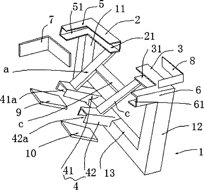
[0022] Such as figure 1 Shown: a kind of bulkhead frame structure of vehicle body, comprises bulkhead frame body 1, left and right vehicle frame upper installation part 2, 3, vehicle frame lower installation part 4, left vehicle frame support plate 5 and right vehicle frame support plate 6, The bulkhead frame body 1 includes left and right support columns 11, 12, a connecting beam 13 is fixed between the left and right support columns 11, 12, and the mounting parts 2, 3 on the left and right vehicle frames are respectively fixed On the left and right support columns 11, 12, there are left and right frame beam installation grooves 21, 31 respectively on the mounting parts 2, 3 of the left and right frames, and the left and right frames The notches of the crossbeam mounting grooves 21, 31 are all facing the crossbeam direction; the left end of the mounting part 2 on the left frame is fixed with a left frame support plate 5 perpendicular to the mounting part 2 on the left frame. ...
Embodiment 2
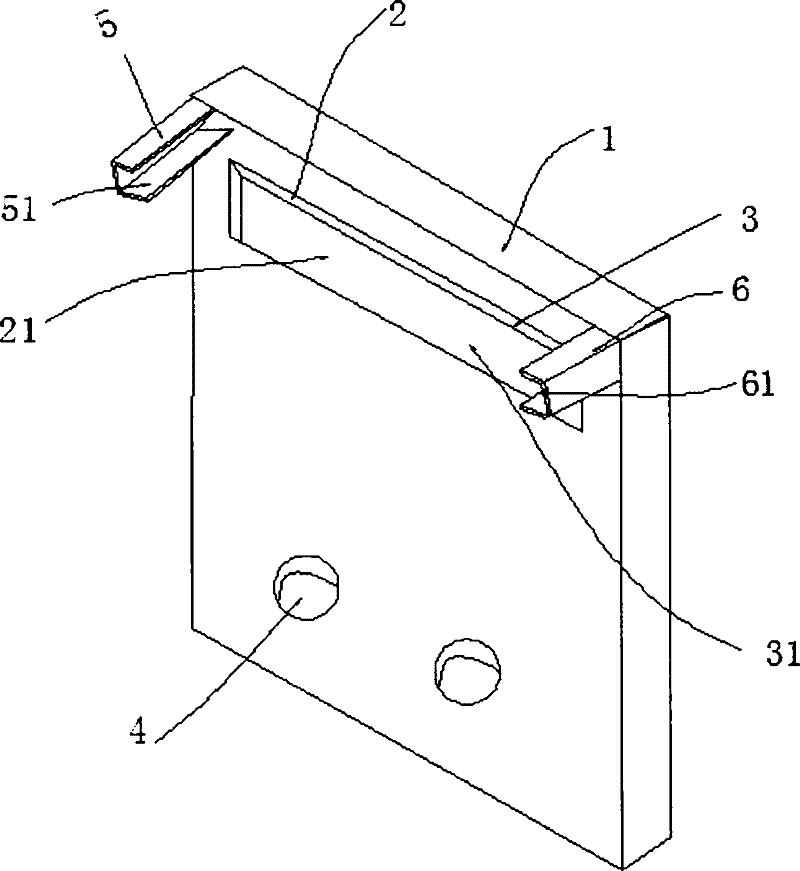
[0025] Such as figure 2Shown: a kind of bulkhead frame structure of vehicle body, comprises bulkhead frame body 1, and this bulkhead frame body 1 is plate-like structure, and left vehicle frame support plate 5 is respectively fixed on the upper left and right two parts of described bulkhead frame body 1 And the right frame support plate 6, on the said left frame support plate 5, there is a left frame longitudinal beam installation groove 51 extending along the longitudinal beam direction, on the said right frame support plate 6, there is a longitudinal The right frame longitudinal beam mounting groove 61 extending in the beam direction is provided with left and right frame upper mounting parts 2 and 3 on the upper part of the bulkhead frame body 1, and the left and right frame upper mounting parts 2 and 3 respectively There are left and right vehicle frame crossbeam installation grooves 21, 31, and the lower installation part 4 of the vehicle frame is provided at the bottom o...
Embodiment 3
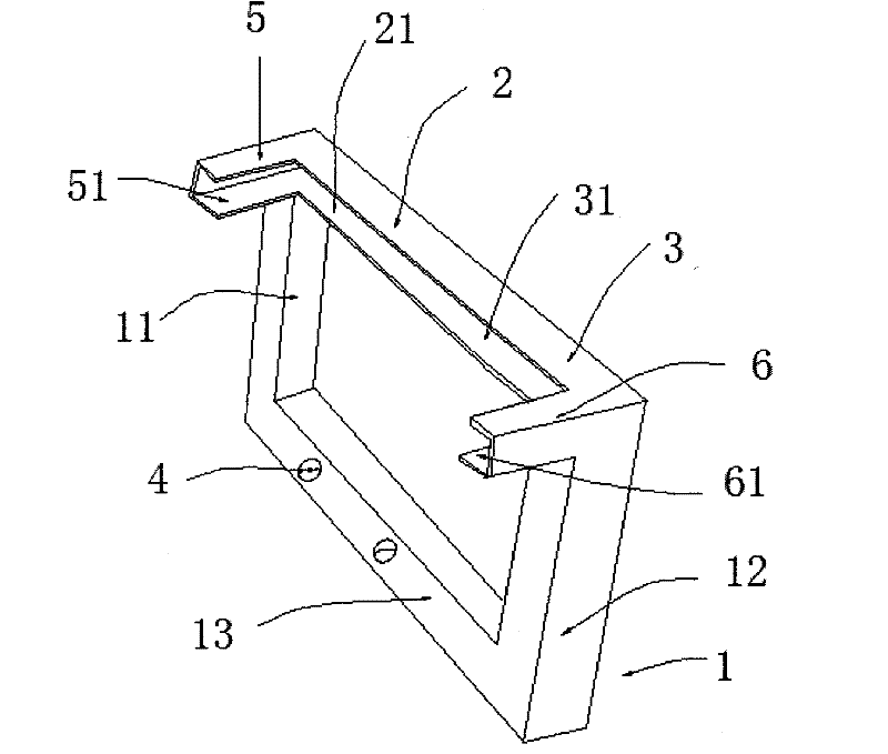
[0027] Such as image 3 Shown: a kind of bulkhead frame structure of vehicle body, comprises bulkhead frame body 1, left and right vehicle frame upper installation part 2, 3, vehicle frame lower installation part 4, left vehicle frame support plate 5 and right vehicle frame support plate 6, The bulkhead frame body 1 is a door frame structure, including left and right support columns 11, 12, a connecting beam 13 is fixed between the left and right support columns 11, 12, and the mounting parts on the left and right vehicle frames 2, 3 are respectively fixed on the left and right support columns 11, 12, and left and right frame crossbeam mounting grooves 21, 31 are respectively opened on the mounting parts 2, 3 of the left and right frames, and the The notches of the left and right frame beam mounting grooves 21, 31 are all facing the beam direction, and the left frame support plate 5 perpendicular to the left frame mounting portion 2 is fixed on the left end of the left frame m...
PUM
 Abstract
Description
Claims
Application Information
 - R&D
- Intellectual Property
- Life Sciences
- Materials
- Tech Scout
- Unparalleled Data Quality
- Higher Quality Content
- 60% Fewer Hallucinations
Browse by: Latest US Patents, China's latest patents, Technical Efficacy Thesaurus, Application Domain, Technology Topic, Popular Technical Reports.
© 2025 PatSnap. All rights reserved.Legal|Privacy policy|Modern Slavery Act Transparency Statement|Sitemap|About US| Contact US: help@patsnap.com