Machine for blasting abrasives

a technology of blasting abrasives and abrasives, which is applied in the direction of grinding drives, grinding machine components, manufacturing tools, etc., can solve the problems of contaminating the area near the machine, deteriorating the seal, and affecting the operation of the door, and achieves the effect of simple structur

Active Publication Date: 2015-05-26
SINTOKOGIO LTD
View PDF7 Cites 4 Cited by
  • Summary
  • Abstract
  • Description
  • Claims
  • Application Information

AI Technical Summary

Benefits of technology

[0026]The present invention has been conceived to solve the above problems. It is, therefore, an object to provide a machine for blasting abrasives with a novel and simple structure that can solve the problem wherein abrasives fall when opening and closing the door for a gateway for a work.
[0029]In the above structure, it is preferable that the jig 15 linearly move up and down so as to be able to adjust the height. The gateway 17 is formed at the location corresponding to the jig 15 that is linearly moving up and down. It has such a size so as to enable the work W to protrude by means of the jig 15 from the chamber 11. Since one driving source can be used for bringing the work in and taking it out and for adjusting the height of it during the process, the structure of the machine for blasting abrasives can be simplified. Further, energy can be saved.
[0030]In the above structure, it is preferable that the door 19 be shaped as a dome (hemisphere). By doing so, any error in the size of the door 19 or the opening that is manufactured may be compensated for. A misalignment of the motion of the door 19 in relation to the gateway 17 may be also compensated for. Thus sealing by the door can be reliable and stable.
[0031]Furthermore, in the above structure, it is preferable that an auxiliary mechanism 29 for shutting the door that functions under a vacuum be provided on the chamber 11, as, for example, shown in FIG. 5. The auxiliary mechanism 29 has a plurality of cylinders 31 that are located under the periphery of the door 19. The tips of piston rods 31a press the periphery of the door. In the cylinder 31 a communication tube 33 that communicates with the outside of the chamber 11 is connected to the compressing chamber 31b that pushes out the piston rod 31a. A vent 35 that communicates with the inside of the chamber 11 is formed in a back-pressure chamber 31c. Since the pressure in the chamber 11 becomes negative during the process because of the operation of a dust collector, etc., sealing may be more reliable and stable (i.e., an increase of the pressure for sealing).

Problems solved by technology

However, the above door has the following problems.
Thus the blasting materials on the surface of the door may slide into the sealing surface to deteriorate the seal.
They may fall out of the machine, to contaminate the area near the machine.
These have been problems.
That causes a problem in the operability of the door.”
Thus, when the door is opened, blasting materials (abrasives) that have adhered near the door may fall outside the chamber.
However, it is not intended nor suggested to dispose a gateway for a work with a door on the upper wall to prevent abrasives from dropping outside the machine when opening or closing the door.
However, when shot peening is carried out where fine abrasives (shots) are used, the shots may penetrate the gap between the inner surface of the gateway and the opposing outer surface of the door.
Thus a problem such as a bite by the abrasives may occur there.

Method used


Image

  • Machine for blasting abrasives
  • Machine for blasting abrasives
  • Machine for blasting abrasives

Examples


Embodiment Construction

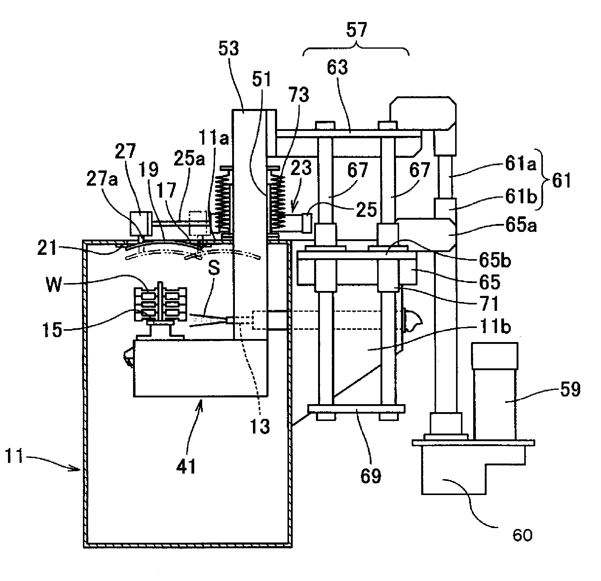
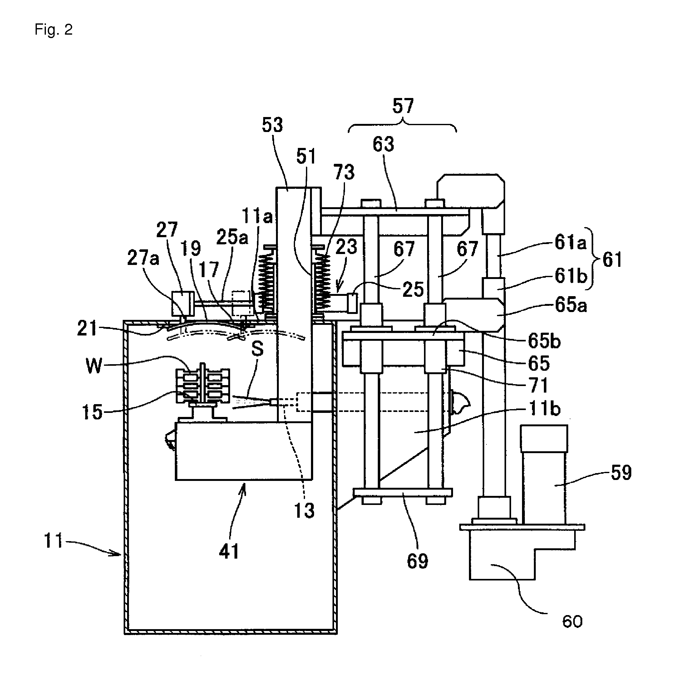
[0052]An embodiment of the machine for blasting abrasives (a machine for shot peening) of the present invention is illustrated in FIGS. 2 and 3.

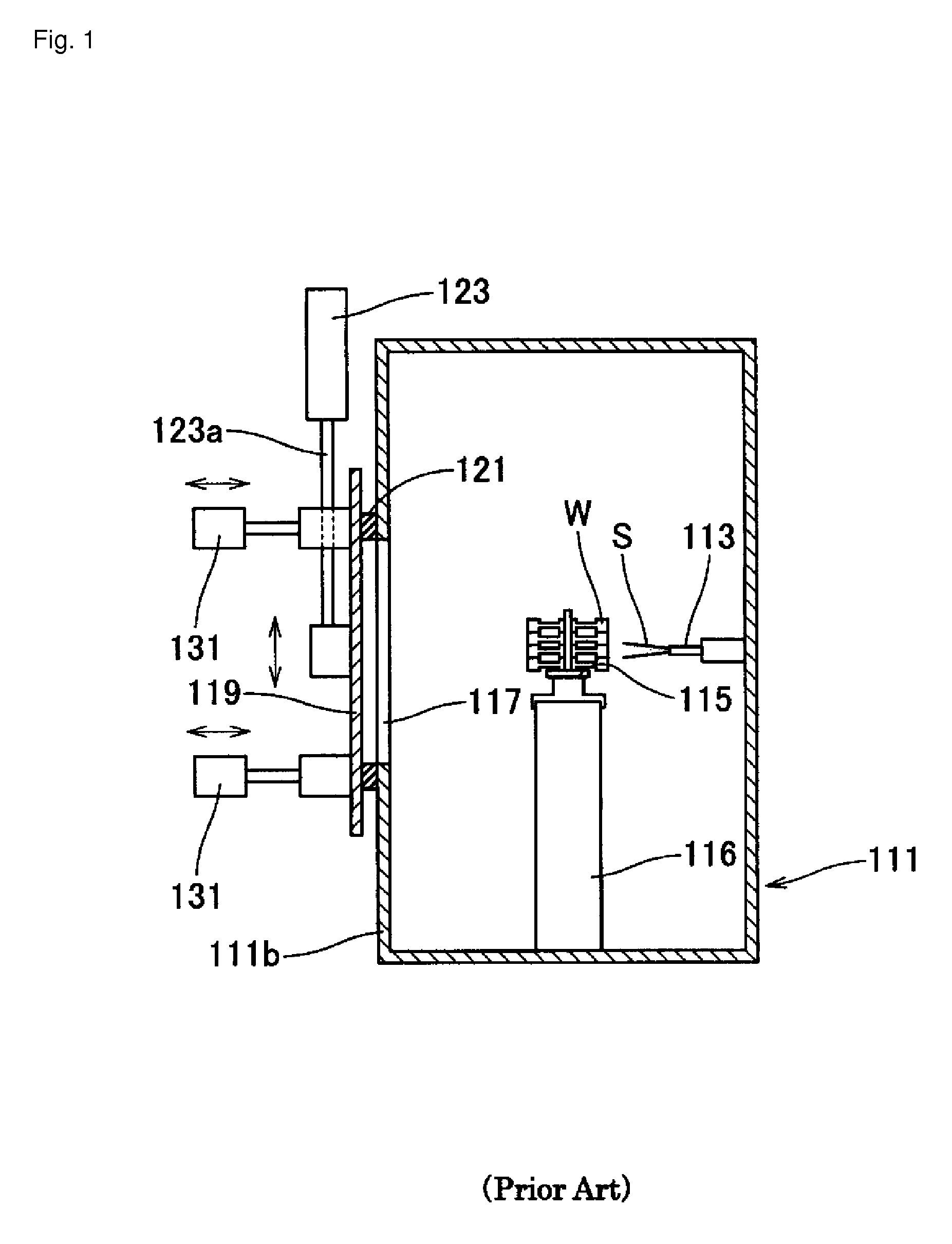
[0053]The machine for blasting abrasives basically comprises a chamber 11 for processing, a nozzle 13 for shooting abrasives (shots) S onto a work W, and a jig 15 for holding the work W. The nozzle 13 is located within the chamber 11. The height of the jig 15 is adjustable so as to keep the work W in the position to face the nozzle 13. A gateway 17 for the work is formed in the chamber 11. It is opened and closed by a door 19. This machine for blasting abrasives has the same structure as a prior-art machine for blasting abrasives.

[0054]The gateway 17 is formed in the ceiling 11a of the chamber 11. The gateway 17 is located at a position corresponding to the jig 15 that is linearly moving up and down. Its size enables the work W to protrude from the chamber 11 by means of the jig 15. The door 19 is provided within the chamber 11, specifically...


PUM


Abstract

The object of the present invention is to provide a machine for blasting abrasives that has a simple structure and that solves the problem of abrasives falling when the door for the gateway for the work is opened or closed. The machine for blasting abrasives comprises a chamber 11 for processing, a nozzle 13 that is provided within the chamber 11 for shooting the abrasives (shots) S onto the work W, and a jig 15 for holding the work W at a position facing the nozzle 13. A gateway 17 with a door 19 is formed in the ceiling 11a of the chamber 11. The size of the gateway 17 enables the work W to protrude from the chamber 11 by means of the jig 15 at a position corresponding to the jig 15 that is linearly moving up and down. The door 19 is provided within the chamber 11 so as to seal the gateway by linearly moving up and down and so as to create a vacant plane on the gateway for passing the work by horizontally moving.

Description

TECHNICAL FIELD[0001]The present invention relates to a machine for blasting abrasives that is used for processing a surface of a work (an object to be processed), such as by surface modification, grinding, and burring. The machine shoots shots (abrasives) onto a work just as a machine for shot-peening or shot-blasting does.[0002]The term “abrasives” means any materials to be shot by energy that is provided by an airflow, a fluid flow (such as a water flow), or centrifugal forces. The materials are used for processing a surface of a work such as shot blasting and shot peening. Thus, the abrasives include any materials to be shot, such as fine grains, grits, and cut wires, as well as shots (small particles).BACKGROUND ART[0003]FIG. 1 illustrates a schematic diagram of a prior-art machine for blasting abrasives that is used for shot blasting.[0004]The machine for blasting abrasives comprises a nozzle (a nozzle for shooting) 113 for shooting abrasives onto a work, a jig 115 for holding...

Claims


Application Information

Patent Timeline
Patent Type & Authority Patents(United States)
IPC IPC(8): B24C9/00B24C3/22
CPCB24C9/00B24C3/22
Inventor KOBAYASHI, YUJINAKATA, TAKEYOSHI
Owner SINTOKOGIO LTD
Why Eureka
Try Eureka