Adjustable crankshaft turning tool

An adjustable crankshaft technology, applied in the direction of manufacturing tools, hand-held tools, etc., can solve the problems of occupying production space, affecting production rhythm, and wasting time, saving space, avoiding too many crankshaft tools, and saving waste.

Pending Publication Date: 2020-09-25
GUANGXI YUCHAI MASCH CO LTD
View PDF0 Cites 4 Cited by
  • Summary
  • Abstract
  • Description
  • Claims
  • Application Information

AI Technical Summary

Problems solved by technology

The disc crankshaft device of the V-type engine realizes the rotation of the crankshaft by means of a sleeve and a wrench. The existing disc crank tool is dedicated to a special machine. In the case of crankshaft tools, on the one hand, changing tools back and forth causes a waste of time; on the other hand, too many tools occupy the production space, and there may be situations in the production site where the production cycle is affected due to looking for tools.

Method used


Image

  • Adjustable crankshaft turning tool
  • Adjustable crankshaft turning tool
  • Adjustable crankshaft turning tool

Examples


Embodiment Construction

[0018] The specific embodiments of the present invention will be described in detail below in conjunction with the accompanying drawings, but it should be understood that the protection scope of the present invention is not limited by the specific embodiments.

[0019] Unless expressly stated otherwise, throughout the specification and claims, the term "comprise" or variations thereof such as "includes" or "includes" and the like will be understood to include the stated elements or constituents, and not Other elements or other components are not excluded.

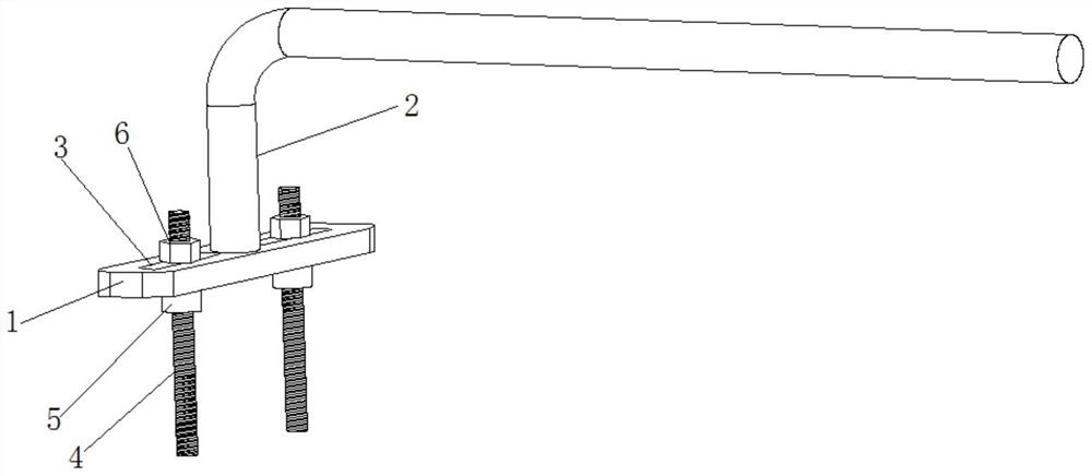
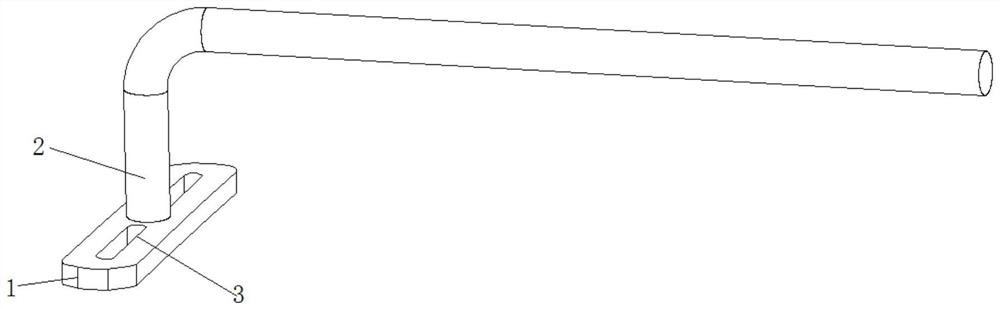
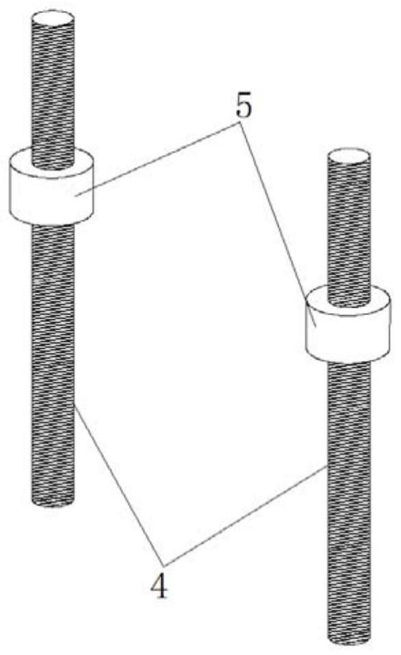
[0020] Such as Figure 1 to Figure 3 as shown, figure 1 It is a schematic diagram of the overall three-dimensional structure of the adjustable disc crank tool according to an embodiment of the present invention. figure 2 It is a partial three-dimensional structure schematic diagram of an adjustable disc crank tool according to an embodiment of the present invention. image 3 It is a structural schematic diagram of an ad...


PUM


Abstract

The invention discloses an adjustable crankshaft turning tool. The adjustable crankshaft turning tool includes a fixing seat, a fixing seat handle, two adjusting holes and at least one adjusting rod.The fixing seat handle is installed at the top center of the fixing seat. The two adjusting holes are separately opened on the top of the fixing seat and located on both sides of the fixing seat handle. The at least one adjusting rod is installed in the adjusting hole, the adjusting rod is provided with a limiting block at the bottom end of the adjusting hole, and an adjusting nut is sleeved on the adjusting rod at the top end of the adjusting hole. Therefore, the adjustable crankshaft turning tool disclosed by the invention can be applied to different models, and the work efficiency is improved.

Description

technical field [0001] The invention relates to the technical field of engine manufacture, in particular to an adjustable disc crankshaft tool. Background technique [0002] When assembling the crank connecting rod mechanism of an internal combustion engine on site, employees need to use a crankshaft tool to turn the crankshaft to complete the assembly of pistons of different cylinders or measure the rotational moment of the crankshaft. [0003] Patent No. 201620697986.7 In the disk crankshaft device of the V-type engine, the disk crankshaft device includes: a rotating plate, which is plate-shaped, and the two sides of the rotating plate are respectively provided with connecting pin holes, and the middle part of the rotating plate is provided with joint screws. Holes; connecting pins arranged in pairs, which are cylindrical, one end of the connecting pin is tapered, used to insert into the surface hole at the big end of the crankshaft to drive the crankshaft to rotate, the o...

Claims


Application Information

Patent Timeline
Patent Type & Authority Applications(China)
IPC IPC(8): B25B27/00
CPCB25B27/00
Inventor 杨云江马庆高睿智
Owner GUANGXI YUCHAI MASCH CO LTD
Why Eureka
Try Eureka