Bridge equipment

A kind of equipment and bridge technology, applied in the field of bridge equipment, can solve the problems of reduced service life of electrical facilities, unstable power supply connection, different cable lengths, etc., and achieve the effect of reducing the incidence rate, simple and convenient locking operation, and simple and convenient unlocking operation

Inactive Publication Date: 2017-10-17
奚聪聪
View PDF0 Cites 1 Cited by
  • Summary
  • Abstract
  • Description
  • Claims
  • Application Information

AI Technical Summary

Problems solved by technology

[0002] The construction of the bridge requires a large number of electrical facilities. The electrical facilities are energized by directly inserting the contact arm connected to it into the electrical connection hole of the electrical socket and then energized. The electrical socket is connected to the mains and will always be powered , although this plug-in method is more convenient to operate, the length of the cable between the contact arm and the electrical equipment is different, and there is no other locking device to lock the contact arm after the contact arm is inserted into the electrical connection hole. When kicking and bumping by mistake, the contact arm will be separated from the electrical connection hole, which will lead to a sudden power failure of the electrical equipment, so that the service life of the electrical equipment will be reduced, and if it is serious, it will directly cause the electrical equipment to be burned. The plug-in cooperation between some contact arms and electrical connection holes has unstable power supply connections. In addition, when the electrical equipment is not in use, the contact arms are often pulled out from the electrical connection holes, which will cause the electrical connection holes to be damaged. It is easy to cause electric shock accidents, and there is a great potential safety hazard. Moreover, when the electrical equipment needs to be powered off and pulled out after the electrical facilities are used, a large force needs to be applied to the contact arm, and it is more laborious to pull out the contact arm.

Method used


Image

  • Bridge equipment
  • Bridge equipment
  • Bridge equipment

Examples


Embodiment Construction

[0017] The preferred embodiments of the present invention will be described in detail below in conjunction with the accompanying drawings, so that the advantages and features of the present invention can be more easily understood by those skilled in the art, so as to define the protection scope of the present invention more clearly.

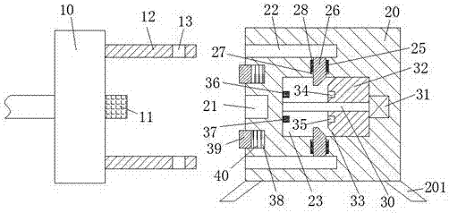
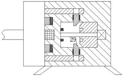
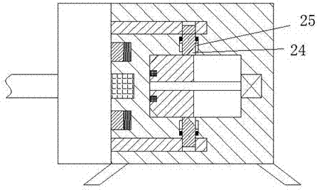
[0018] refer to Figure 1-4 The shown bridge equipment includes an electric connection part connected to electrical equipment through cables and an electric socket connected to the mains. The electric connection part includes a handle 10, and the right end of the handle 10 is Two bolts 12 are arranged at the front and rear ends equally, and a locking groove 13 is arranged at the right end of each of the two bolts 12, and a contact arm 11 is arranged at the center of the right end surface of the handle 10. The socket includes a frame body 20, and a support column 201 is fixedly installed around the bottom of the frame body 20, and the bottom of th...


PUM


Abstract

The invention discloses a bridge device, which comprises an electric connection part connected with electrical equipment through a cable and an electric connection seat connected with the mains. Two bolts are arranged on opposite ends, each of the two bolts is provided with a locking groove at the right end, and the center of the right end surface of the handle is provided with a contact arm, and the electric socket includes a frame body, The support column is fixedly installed around the bottom of the frame body, the bottom of the support column is opened outwards, and the left end surface of the frame body is provided with an electrical connection hole that opens to the left and is used to cooperate with the contact arm. The invention has a simple structure, good power supply stability, avoids electric shock accidents when plugging and unplugging the electric connector, increases the safety of the bridge construction, and the whole device operates safely and reliably. It is convenient and labor-saving to pull out the connecting part.

Description

technical field [0001] The invention relates to the field of bridges, in particular to bridge equipment. Background technique [0002] The construction of the bridge requires a large number of electrical facilities. The electrical facilities are energized by directly inserting the contact arm connected to it into the electrical connection hole of the electrical socket and then energized. The electrical socket is connected to the mains and will always be powered , although this plug-in method is more convenient to operate, the length of the cable between the contact arm and the electrical equipment is different, and there is no other locking device to lock the contact arm after the contact arm is inserted into the electrical connection hole. When kicking and bumping by mistake, the contact arm will be separated from the electrical connection hole, which will lead to a sudden power failure of the electrical equipment, so that the service life of the electrical equipment will b...

Claims


Application Information

Patent Timeline
Patent Type & Authority Applications(China)
IPC IPC(8): H01R13/633H01R13/635H01R13/639H01R13/70
CPCH01R13/639H01R13/6335H01R13/635H01R13/701
Inventor 奚聪聪
Owner 奚聪聪
Why Eureka
Try Eureka