Supercharge Your Innovation With Domain-Expert AI Agents!

Vehicle Lamps

A technology for lamps and vehicles, applied in the direction of headlights, vehicle parts, lighting and heating equipment, etc., can solve problems such as difficulties in vehicle lamps and lanterns, and achieve the effects of good optical axis adjustment and compact composition accuracy.

Active Publication Date: 2019-11-08
KOITO MFG CO LTD
View PDF4 Cites 0 Cited by
  • Summary
  • Abstract
  • Description
  • Claims
  • Application Information

AI Technical Summary

Problems solved by technology

[0007] However, with such a configuration, it is necessary to secure a space between the optical units for each optical unit to rotate, so it is difficult to configure a vehicle lamp compactly.

Method used


Image

  • Vehicle Lamps
  • Vehicle Lamps
  • Vehicle Lamps

Examples


Embodiment Construction

[0084] Hereinafter, embodiments of the present invention will be described with reference to the accompanying drawings. In the following embodiments, although various limitations are made to constituent elements, types, combinations, shapes, relative arrangements, etc., these are merely examples, and the present invention is not intended to limited to this.

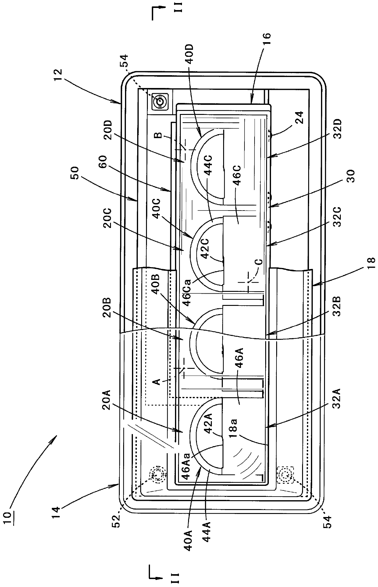
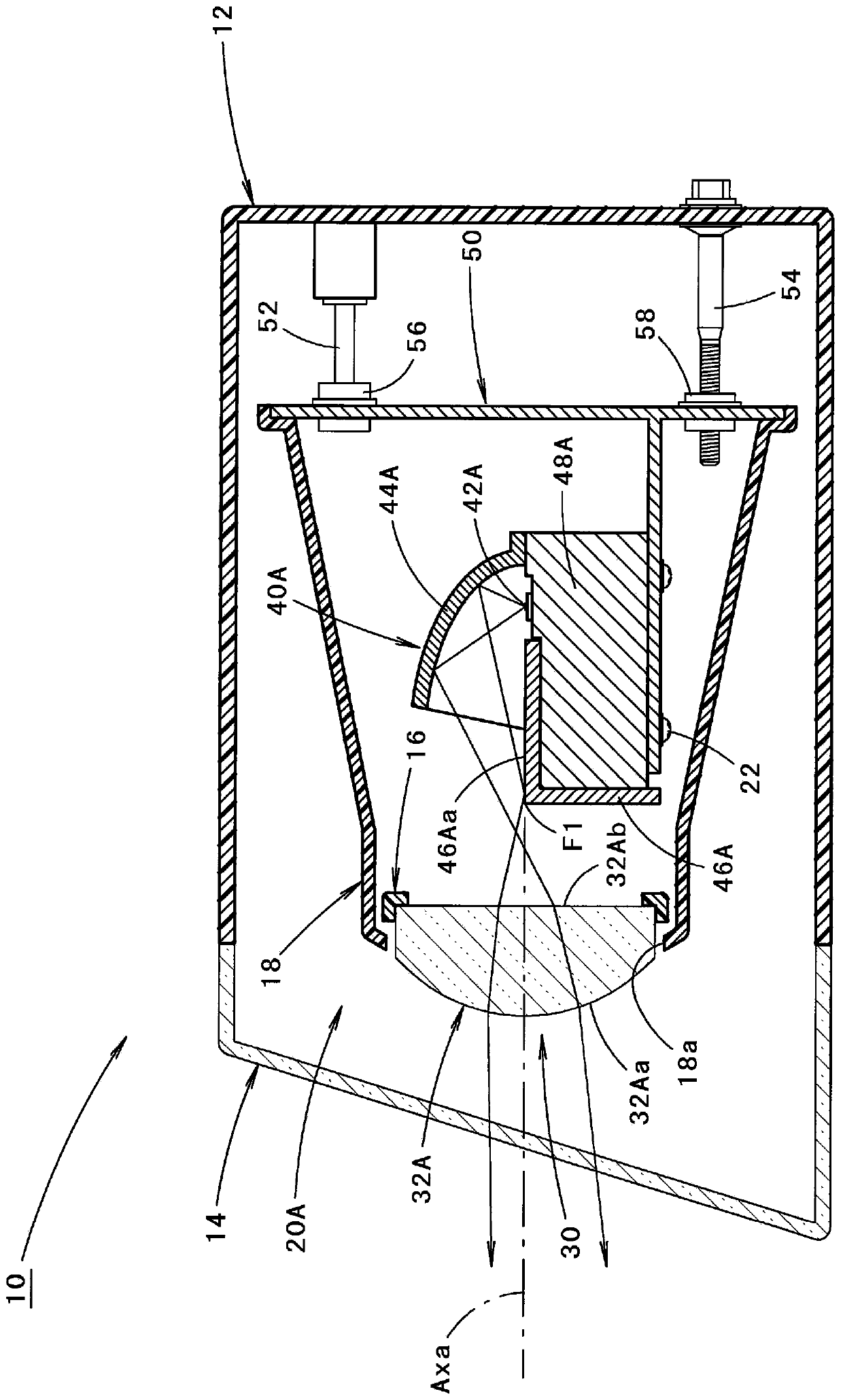
[0085] figure 1 It is a front view showing a vehicle lamp 10 according to an embodiment of the present invention. again, figure 2 yes figure 1 The Ⅱ-Ⅱ line sectional view.

[0086] As shown in these figures, the vehicle lamp 10 according to the present embodiment is a headlight arranged at the left front end portion of the vehicle, and has a structure capable of forming a low beam light distribution pattern.

[0087] As a vehicle lamp 10, in figure 2 Among them, the direction indicated by X is "front" (even if it is a vehicle, it is "front"), and the direction indicated by Y is "left direction" orthogonal to "front...


PUM


Abstract

The present disclosure provides a vehicle lamp including: a main bracket pivotably supported to a lamp body; and a sub-bracket pivotably supported to the main bracket. A first optical unit is supported directly to the main bracket, and three second optical units are supported to the main bracket via the sub-bracket. An optical axis adjustment for the first optical unit and the three second optical units is collectively performed by pivoting of the main bracket, and an optical axis deviation between the first optical unit and the three second optical units is corrected by pivoting of the sub-bracket.

Description

technical field [0001] The present invention relates to a vehicle lamp provided with a plurality of optical units. Background technique [0002] Conventionally, a vehicle lamp configured to form a desired light distribution pattern by emitted light from a plurality of optical units is known. [0003] Also, as such a vehicle lamp, a vehicle lamp in which a main frame supporting a plurality of optical units is supported so as to be rotatable relative to a lamp body is known. [0004] In "Patent Document 1", in such a vehicle lamp, it is described that each optical unit is supported so as to be rotatable with respect to the main bracket. [0005] [Patent Document 1] Japanese Patent Laid-Open No. 2005-165590 [0006] In the vehicle lamp described in the above "Patent Document 1", by rotating the main bracket relative to the lamp body, it is possible to collectively perform adjustment of the optical axes of the plurality of optical units, and by rotating each optical unit relat...

Claims


Application Information

Patent Timeline
Patent Type & Authority Patents(China)
IPC IPC(8): F21S41/36F21S41/147F21S45/47F21S41/26F21S41/19F21S41/32F21S41/40F21S45/49B60Q1/06F21W102/00
CPCB60Q1/0683F21S41/148F21S41/192F21S41/26F21S41/321F21S41/365F21S41/40F21S45/47F21S45/49
Inventor 新井创
Owner KOITO MFG CO LTD
Features
  • R&D
  • Intellectual Property
  • Life Sciences
  • Materials
  • Tech Scout
  • Unparalleled Data Quality
  • Higher Quality Content
  • 60% Fewer Hallucinations
Learn More