
Laser marking method and marking device for IC card

A laser marking method and laser marking technology, which are applied in the field of IC card laser marking methods and marking devices, can solve the problems of low equipment production capacity and low marking efficiency of marking devices, so as to improve production capacity and reduce laser marking. The effect of marking the average time and improving the efficiency of laser marking

Active Publication Date: 2017-10-24
沈阳友联电子装备有限公司
View PDF10 Cites 7 Cited by
  • Summary
  • Abstract
  • Description
  • Claims
  • Application Information

AI Technical Summary

Problems solved by technology

[0005] In view of this, the object of the present invention is to provide a kind of IC card laser marking method and marking device, to solve the existing laser marking method and marking device marking efficiency is low, less equipment capacity and other problems

Method used


Image

  • Laser marking method and marking device for IC card
  • Laser marking method and marking device for IC card
  • Laser marking method and marking device for IC card

Examples


Embodiment Construction

[0028] The present invention will be further explained below in conjunction with specific embodiments, but the present invention is not limited thereto.

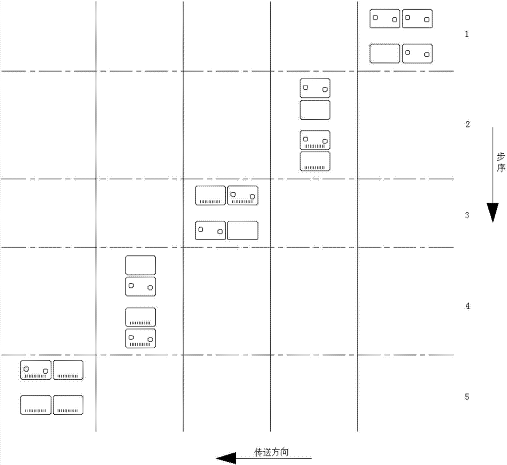
[0029] In order to solve the problems of low IC card laser marking efficiency and low equipment capacity in the past, the present invention provides an IC card laser marking method, which is used to perform double-sided marking on the IC card to be marked with the same side facing the same side. Marking, specifically includes the following steps:

[0030] 1) Turn over the intervals of the IC cards to be marked, so that the IC cards are arranged alternately on the front and back sides;

[0031] 2) Send the IC cards to be marked alternately arranged on the front and back to the first laser marking device in sequence. After receiving the IC cards, the first laser marking device will move the IC cards to the working area On position I and position II, where there is at most one IC card on position I and position II with the sam...


PUM


Abstract

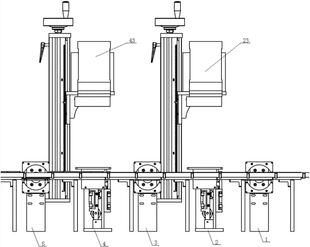
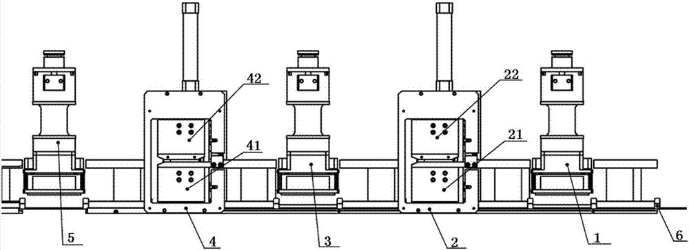
The invention discloses a laser marking method and a marking device for an IC card. The laser marking method comprises the following steps: 1) overturning the IC cards at interval; 2) transmitting the IC cards to a first laser marking device in sequence; 3) performing first marking; 4) overturning the IC cards which are marked in first marking, and transmitting the IC cards to a second laser marking device in sequence; 5) performing second marking; 6) overturning the IC cards at interval. The laser marking device for an IC card comprises a first turnover device, a first laser marking device, a second turnover device, a second laser marking device, a third turnover device, and a transmission belt. The first laser marking device comprises a station I, a station II, and first laser. The second laser marking device comprises a station I, a station II, and second laser. The laser marking method and the marking device for an IC card can reduce average time of laser marking, greatly improve laser marking efficiency, and obviously improve productivity.

Description

technical field [0001] The invention belongs to the technical field of IC card making, and particularly provides an IC card laser marking method and a marking device. Background technique [0002] The size of the IC card is 85.6mm×54mm according to the national unified standard. The card base material of the IC card is PVC (polyvinyl chloride), ABS and other plastics or paper. The IC cards on the market are divided into single-card single-core or one-card multi-core. At present, the whole process of IC card personalized data writing equipment is as follows: card issuance - main belt stepping - card writing station - laser marking - sequential recycling. According to the production requirements, it is possible to carry out laser marking on both sides of the front and back of the IC card, so the laser marking is divided into five stations. The sequence is: card flip 1 - laser marking 1 - card flip 2 - laser marking Mark 2—Flip 3. At present, the laser only marks one side of a...

Claims


Application Information

Patent Timeline
Patent Type & Authority Applications(China)
IPC IPC(8): B41J2/435B41J3/407B41J3/60
CPCB41J2/435B41J3/407B41J3/60
Inventor 范喜斌
Owner 沈阳友联电子装备有限公司
Learn More