A smart card laser marking method and a laser marking device implementing the method

A laser marking method and laser marking technology are applied in the field of a smart card laser marking method and a laser marking device for implementing the method, which can solve the problems of laser stoppage and increase marking time, etc., so as to improve production efficiency and improve work efficiency. Efficiency, the effect of improving the efficiency of laser marking

Active Publication Date: 2018-01-09
SHENZHEN PIOTEC TECH CO LTD
View PDF9 Cites 0 Cited by
  • Summary
  • Abstract
  • Description
  • Claims
  • Application Information

AI Technical Summary

Problems solved by technology

[0007] In order to solve the problem of increasing the marking time due to the pause of the laser caused by the replacement of the marked smart card, the purpose of the present invention is to provide a smart card laser marking method and a laser marking device for implementing the method

Method used


Image

  • A smart card laser marking method and a laser marking device implementing the method
  • A smart card laser marking method and a laser marking device implementing the method
  • A smart card laser marking method and a laser marking device implementing the method

Examples


Embodiment Construction

[0039] The present invention will be described in further detail below in conjunction with the accompanying drawings.

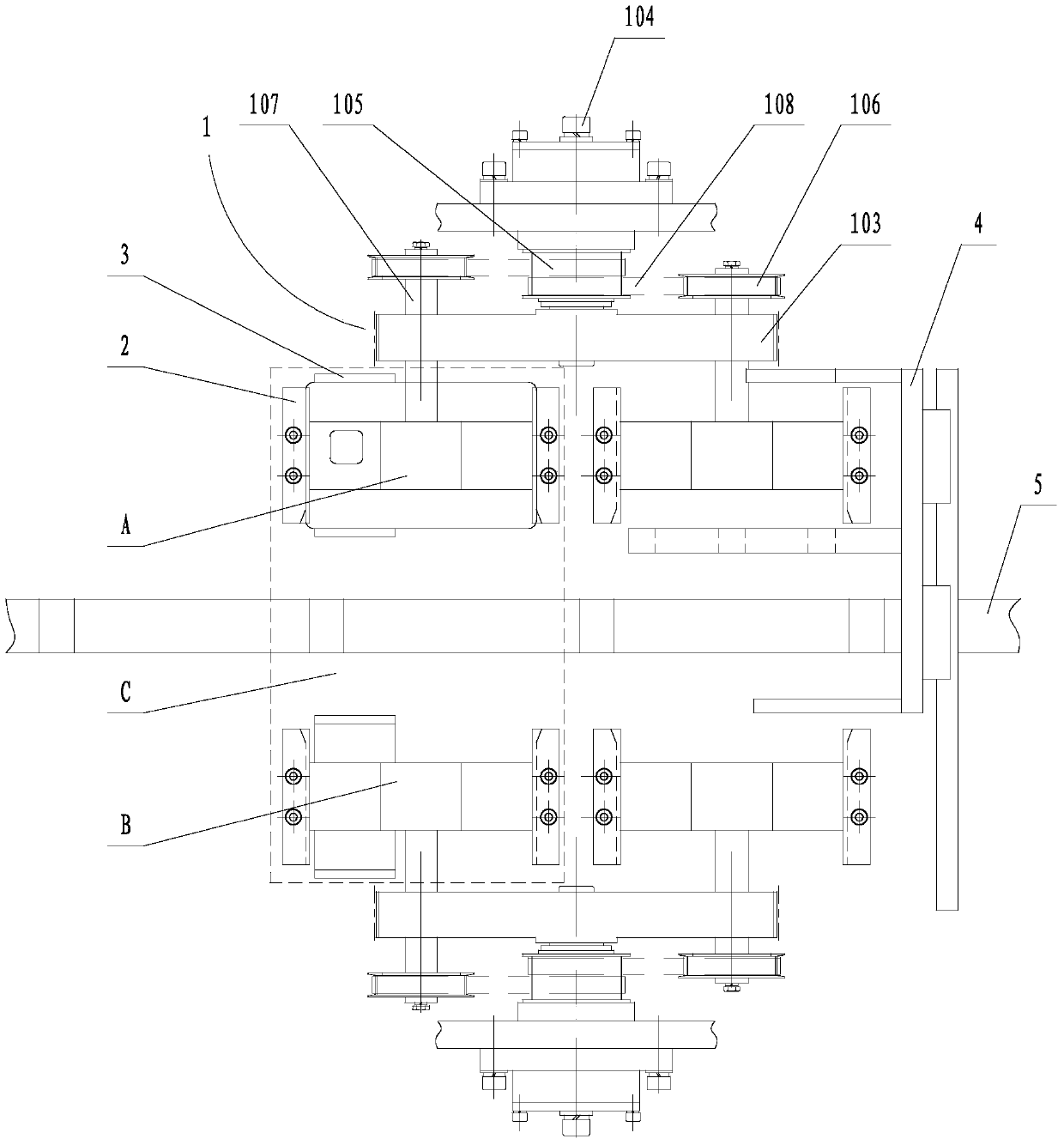
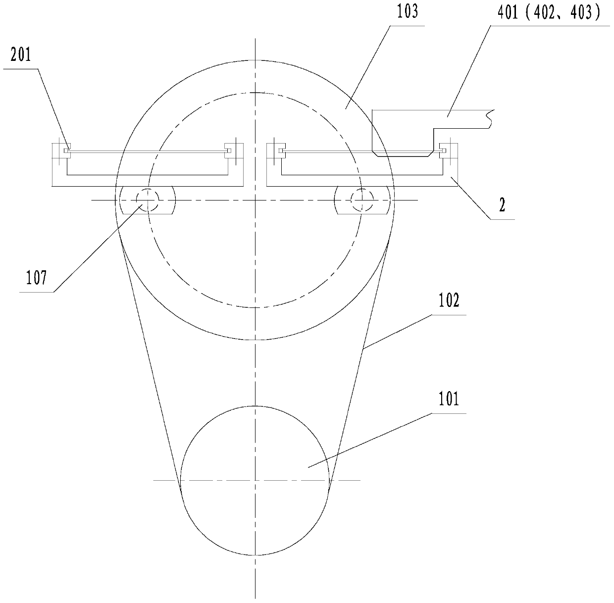
[0040] A group of two laser marking devices are arranged symmetrically on both sides of the conveyor belt 5 for conveying smart cards. Such as figure 1 , figure 2 As shown, each laser marking device includes a rotating mechanism 1 and at least two support clips 2 , and this embodiment takes two support clips as an example, which are respectively a support card A and a support card B. Rotating mechanism 1 comprises driving pulley 101, belt A102 and driven pulley 103, and the driving wheel shaft of driving pulley 101 and the driven wheel shaft 104 of driven pulley 103 are respectively rotated and installed on the rotating mechanism mounting seat. The seat is fixed on the machine platform of the smart card data writing device, and the driving pulley 101 is connected to the power source A (which can be a motor), and is connected to the driven pulley 103 for tr...


PUM


Abstract

The invention relates to an intelligent card laser marking method and a laser marking device for implementing the method. Laser marking devices at the two sides of a conveyor belt of intelligent cards are respectively provided with a rotating mechanism and at least two card holders. The card holders are switched between a card receiving station and a laser marking station under driving of the rotating mechanism. The laser marking devices at the two sides of the conveyor belt are arranged within a laser marking region of one laser. The odd intelligent cards on the conveyor belt are pushed to the rotating mechanism at one side and the even intelligent cards are pushed to the rotating mechanism at the other side in sequence, and are transmitted to the laser marking station with the rotation of the rotating mechanism at each side; and the laser carries out laser marking on the intelligent cards on the laser marking stations at the two sides of the conveyor belt continuously. The intelligent cards on the two laser marking stations can be subjected to laser marking continuously by one laser within the laser marking region; and each intelligent card can be marked within a time at least half of the existing laser marking time, and laser marking efficiency is improved.

Description

technical field [0001] The invention belongs to the field of smart card marking, in particular to a smart card laser marking method and a laser marking device implementing the method. Background technique [0002] At present, one of the main factors affecting the production efficiency of smart cards is laser marking on the surface of smart cards. There are three main problems in the current main laser marking methods: [0003] 1. During laser marking, the equipment needs to stop and wait, and then continue to run after printing is completed; [0004] 2. After printing a smart card, the laser will stop and wait for the next smart card to enter the marking station, and then start printing again; [0005] 3. A set of independent positioning mechanism is required for smart card positioning. Laser marking can only be performed after the mechanism completes the positioning action. [0006] With the increase of laser marking information, the corresponding marking time also incre...

Claims


Application Information

Patent Timeline
Patent Type & Authority Patents(China)
IPC IPC(8): B41J2/435B41J3/407
CPCB41J13/12B41J11/007B41J2/442B41M5/24B41J2/4753B41M5/267
Inventor 芦海斌修庆国
Owner SHENZHEN PIOTEC TECH CO LTD
Why Eureka
Try Eureka