A control method of a dual optical path laser online flight coding system

A control method and dual optical path technology, applied in the field of laser marking, can solve the problems of galvanometer control errors and out-of-synchronization, and achieve the effects of ensuring quality, improving efficiency, and avoiding missing codes

Inactive Publication Date: 2017-10-03
WUHAN LEAD LASER
View PDF8 Cites 0 Cited by
  • Summary
  • Abstract
  • Description
  • Claims
  • Application Information

AI Technical Summary

Problems solved by technology

But its technical difficulty is: because the two laser beams emit light or stop at the same time, and the control between the two vibrating mirrors has an error (such as ms level), it will appear that one of the vibrating mirrors has started during laser coding. running, but the other galvanometer does not move (the focus appears, or even penetrates the product), or one galvanometer has stopped while the other galvanometer is still moving (the code is not completed, there is a missing code), in general Say, there is no synchronization between the two

Method used


Image

  • A control method of a dual optical path laser online flight coding system
  • A control method of a dual optical path laser online flight coding system
  • A control method of a dual optical path laser online flight coding system

Examples


Embodiment Construction

[0014] Below in conjunction with accompanying drawing and specific embodiment the present invention is described in further detail:

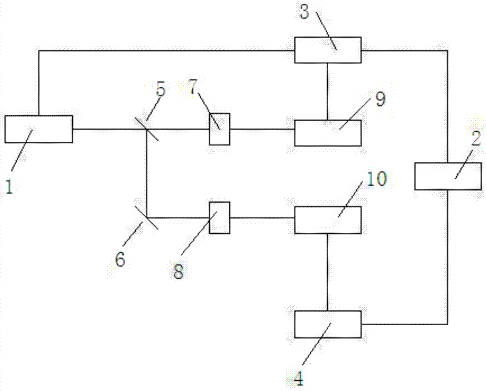
[0015] Such as figure 1 As shown, the double optical path laser on-the-fly coding system of the present invention includes a laser 1, a beam splitter, a light gate, a vibrating mirror and a control system, and also includes a computer 2, and the beam splitter includes a main beam splitter 5 and a secondary beam splitter 6, all The optical shutter includes a main optical shutter 7 and an auxiliary optical shutter 8, the vibrating mirror includes a main vibrating mirror 9 and an auxiliary vibrating mirror 10, the control system includes a main control system 3 and an auxiliary control system 4, and the main control system 3 and the secondary control system 4 are respectively connected with two output ports of the computer 2, the first signal output end of the main control system 3 is connected with the laser 1 control end, and the second signal ou...


PUM


Abstract

The invention relates to the technical field of laser coding, in particular to a dual-optical-path laser on-the-fly coding system and a control method thereof. Including a laser, a computer, a main beam splitter and a sub beam splitter, a main shutter and a sub shutter, a main vibrating mirror and a sub vibrating mirror, a main control system and a sub control system, the main control system and the sub control system are respectively connected with the computer The two output ports are connected, the signal output end of the main control system is respectively connected with the laser control end, the main oscillating mirror control end, and the main optical gate control end, and the auxiliary control system signal output end is respectively connected with the auxiliary optical gate and the auxiliary galvanometer. Taking the control of the laser beam as the timing point, the timing points of the two galvanometers are separately controlled and adjusted through the main control system and the sub-control system, so that the timing points of the two galvanometers are synchronized with the laser, thereby avoiding missing codes, The key phenomenon improves the efficiency of laser marking and ensures the quality of products.

Description

technical field [0001] The invention relates to the technical field of laser coding, in particular to a control method of a dual-optical-path laser on-the-fly coding system. Background technique [0002] In the field of food, product labeling is an essential link. Single optical path on-the-fly laser marking system is becoming more and more common in product identification in the food field. In some cases, the individual packages run side by side on the production line at high speed. Using a single optical path online flying laser coding system cannot meet the high-speed operation of the production line. Sometimes the individual packages running side by side have a large distance, and the packaging running side by side cannot be coded at the same time. object individual. For this reason, the dual-optical-path laser marking technology emerges. The dual-optical-path laser marking technology uses a high-power laser to split into two laser beams. Each path of laser is assembl...

Claims


Application Information

Patent Timeline
Patent Type & Authority Patents(China)
IPC IPC(8): B41J29/38B41J2/435
Inventor 柯西军
Owner WUHAN LEAD LASER
Why Eureka
Try Eureka