
Laser marking control method and device and computer storage medium

A computer storage and laser marking technology, applied in the marking field, can solve problems such as low laser marking efficiency and invalid marking paths, and achieve the effect of reducing invalid marking paths and improving efficiency

Active Publication Date: 2021-11-12
SHENZHEN TETELASER TECH CO LTD
View PDF7 Cites 0 Cited by
  • Summary
  • Abstract
  • Description
  • Claims
  • Application Information

AI Technical Summary

Problems solved by technology

[0002] During laser marking, marking is carried out line by line according to the pattern, but when there is an empty jump area in the pattern that does not need to be marked, the marking path will also pass through the empty jump area that does not need to be marked, and then some Ineffective marking path, resulting in low efficiency of laser marking

Method used


Image

  • Laser marking control method and device and computer storage medium
  • Laser marking control method and device and computer storage medium
  • Laser marking control method and device and computer storage medium

Examples


Embodiment Construction

[0038] It should be understood that the specific embodiments described here are only used to explain the present invention, not to limit the present invention.

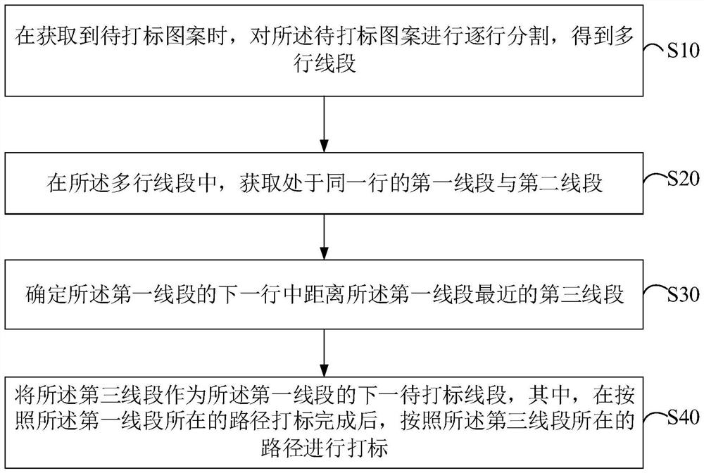
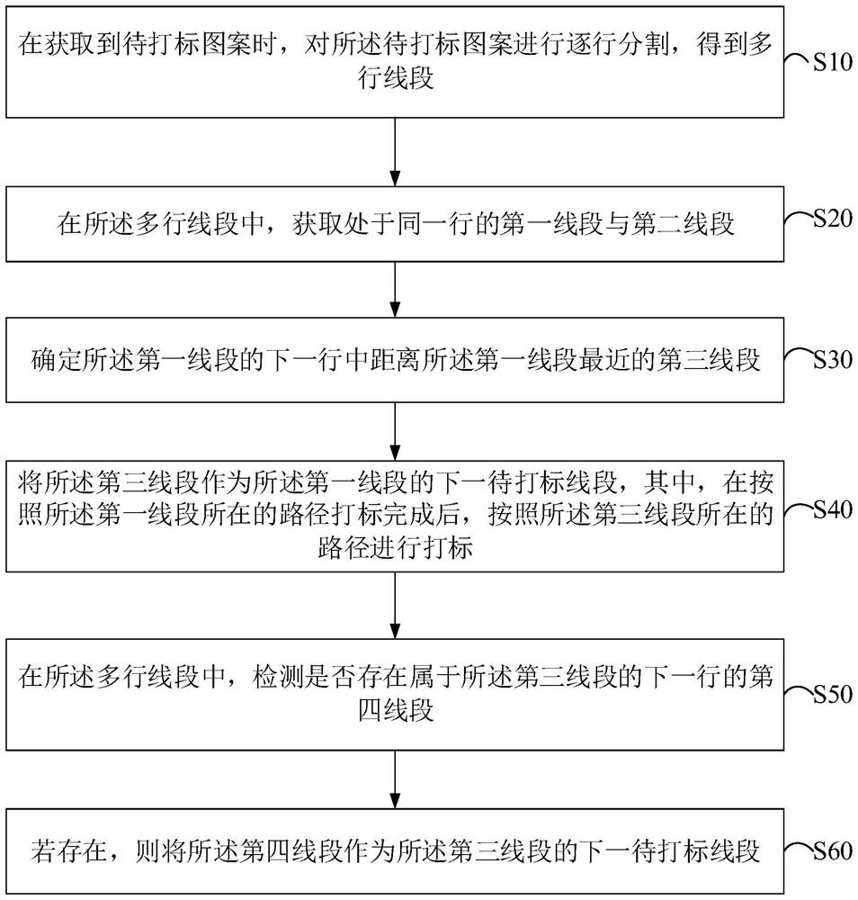
[0039] The embodiment of the present invention provides a solution, by determining the first line segment and the second line segment in the same row in the pattern to be marked, and after marking the first line segment, first mark the next line segment It avoids marking the second line segment through the empty jump area between the first line segment and the second line segment after marking the first line segment, which reduces the invalid marking path and improves the laser marking efficiency. s efficiency.

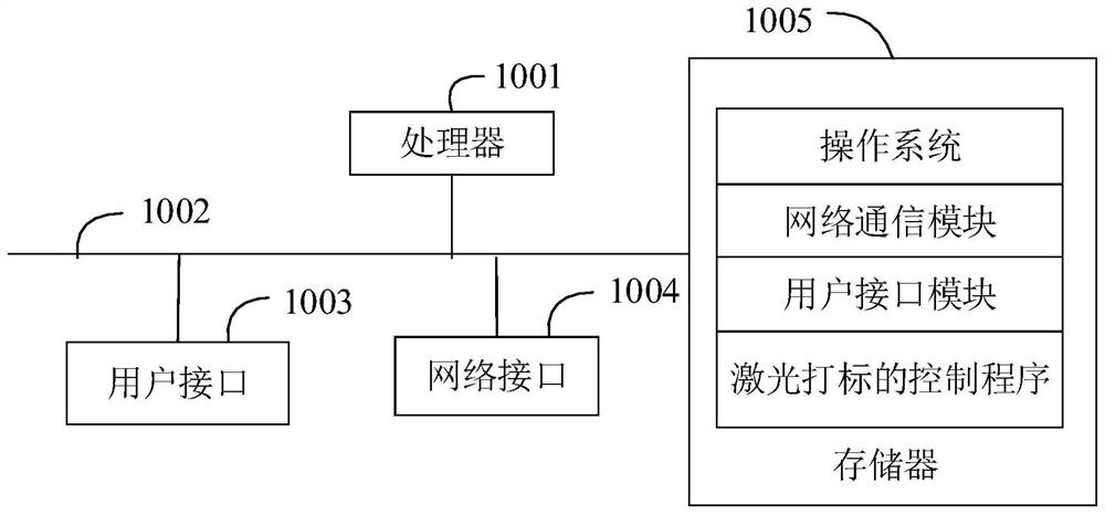
[0040] Such as figure 1 as shown, figure 1 It is a schematic diagram of the terminal structure of the hardware operating environment involved in the solution of the embodiment of the present invention.

[0041] The terminal of the embodiment of the present invention is a control device for laser marking. ...


PUM


Abstract

The invention discloses a laser marking control method. The method comprises the steps of when a to-be-marked pattern is obtained, segmenting the to-be-marked pattern line by line to obtain multiple rows of line segments; in the multiple rows of line segments, acquiring a first line segment and a second line segment which are located in the same row; determining a third line segment closest to the first line segment in the next row of the first line segment; and taking the third line segment as the next to-be-marked line segment of the first line segment, and after marking is completed according to the path where the first line segment is located, carrying out marking according to the path where the third line segment is located. The invention further discloses a laser marking control device and a computer storage medium. According to the laser marking control method and device and the computer storage medium, the first line segment and the second line segment which are located in the same row in the to-be-marked pattern are determined, after marking of the first line segment is completed, marking is carried out on the line segment in the next row firstly, the circumstance that after marking of the first line segment is completed, marking is carried out on the second line segment through a null jump area between the first line segment and the second line segment is avoided, invalid marking paths are reduced, and the laser marking efficiency is improved.

Description

technical field [0001] The invention relates to the technical field of marking, in particular to a laser marking control method, device and computer storage medium. Background technique [0002] During laser marking, marking is carried out line by line according to the pattern, but when there is an empty jump area in the pattern that does not need to be marked, the marking path will also pass through the empty jump area that does not need to be marked, and then some Ineffective marking path, resulting in low efficiency of laser marking. [0003] The above content is only used to assist in understanding the technical solution of the present invention, and does not mean that the above content is admitted as prior art. Contents of the invention [0004] The main purpose of the present invention is to provide a laser marking control method, device and computer storage medium, aiming at reducing invalid marking paths and improving the efficiency of laser marking. [0005] In ...

Claims


Application Information

Patent Timeline
Patent Type & Authority Applications(China)
IPC IPC(8): B23K26/362B23K26/70G06T7/10
CPCB23K26/362B23K26/702G06T7/10B23K2101/007
Inventor 杨勇潘建北周红林周学慧张凯
Owner SHENZHEN TETELASER TECH CO LTD
Learn More