Laser marking method, laser marking equipment and system

A laser marking method and technology of laser marking equipment, which are applied in the field of laser marking, can solve problems such as inability to adapt to product conveying speed and low laser marking efficiency, so as to increase the effective marking range, improve efficiency, and improve accuracy rate effect

Active Publication Date: 2021-09-24
HANS LASER TECH IND GRP CO LTD
View PDF0 Cites 0 Cited by
  • Summary
  • Abstract
  • Description
  • Claims
  • Application Information

AI Technical Summary

Problems solved by technology

[0005] The technical problem to be solved by the present invention is to provide a laser marking method for the above-mentioned defects of the prior art, which overcomes the problem that the center distance of adjacent products is much smaller than that of the laser head when laser marking certain small-sized products. Marking range, a single laser machine cannot adapt to higher product delivery speeds, and the overall laser marking efficiency is low
[0006] The technical problem to be solved by the present invention is to provide a laser marking device for the above-mentioned defects of the prior art, which overcomes the problem that the center distance of adjacent products is much smaller than that of the laser head when laser marking certain small-sized products. Marking range, a single laser machine cannot adapt to higher product delivery speeds, and the overall laser marking efficiency is low
[0007] The technical problem to be solved by the present invention is to provide a laser marking system for the above-mentioned defects of the prior art, which overcomes the problem that the center distance of adjacent products is much smaller than that of the laser head when laser marking certain small-sized products. Marking range, a single laser machine cannot adapt to higher product delivery speeds, and the overall laser marking efficiency is low

Method used


Image

  • Laser marking method, laser marking equipment and system
  • Laser marking method, laser marking equipment and system
  • Laser marking method, laser marking equipment and system

Examples


Embodiment Construction

[0036] Now in conjunction with the accompanying drawings, the preferred embodiments of the present invention will be described in detail.

[0037] Such as figure 1 As shown, the present invention provides a preferred embodiment of a laser marking method.

[0038] A laser marking method, comprising the steps of:

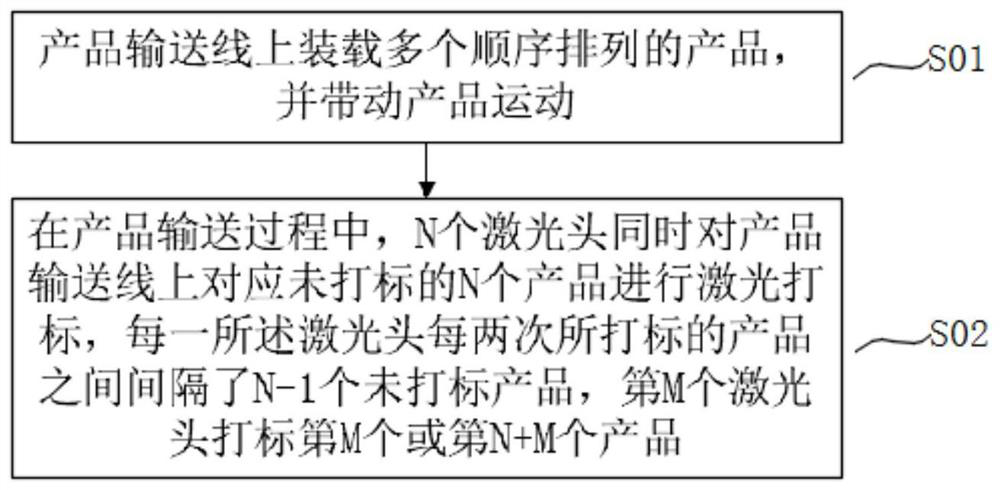
[0039] Step S01, loading a plurality of sequentially arranged products on the product conveying line, and driving the products to move.

[0040] Step S02. During the product conveying process, N laser heads perform laser marking on the corresponding unmarked N products on the product conveying line at the same time, and the products marked by each laser head every two times are separated by For N-1 unmarked products, the Mth laser head marks the Mth or N+Mth product.

[0041] Among them, N≥3, M≤N, and M is a positive integer, such as 1, 2, 3....

[0042] Through the laser marking method, for some small-sized products, when the center distance between adjacent prod...


PUM


Abstract

The invention relates to the technical field of laser marking, in particular to a laser marking method, comprising the steps of: loading a plurality of sequentially arranged products on a product conveying line, and driving the products to move; during the product conveying process, N laser heads simultaneously On the product conveying line, laser marking is carried out corresponding to N unmarked products. There are N-1 unmarked products between the products marked by each laser head every two times. The Mth laser head marks Mark the Mth or N+Mth product; where N≥3, M≤N. The invention also relates to a laser marking device and a laser marking system. Use N laser heads and corresponding controllers to jointly control and work together to carry out laser marking on the corresponding unmarked N products on the product conveying line at the same time, increasing the effective marking range of a single laser marking machine and improving The adaptability of laser marking equipment and laser marking system to the conveying speed of products can improve the conveying speed of products and improve the efficiency of laser marking.

Description

technical field [0001] The invention relates to the technical field of laser marking, in particular to a laser marking method, laser marking equipment and a system. Background technique [0002] In the field of laser marking, there are mainly two application methods: static marking and dynamic marking. In static marking applications, there is no relative movement between the product and the laser marking equipment, and the product is switched periodically. It is necessary to wait for loading and unloading between each marking, and the efficiency is slow. During dynamic marking, the product is in a continuous motion state, and each marking can be continuous, without waiting for incoming materials, and the efficiency is higher. When the product, marking time and other conditions are consistent, dynamic marking can achieve higher work efficiency than static marking. [0003] Therefore, when it is necessary to use laser to mark various content on the surface of the product, dy...

Claims


Application Information

Patent Timeline
Patent Type & Authority Patents(China)
IPC IPC(8): B23K26/362B23K26/70
CPCB23K26/361B23K26/70B23K26/702
Inventor 杨威乌军平韩永锋欧阳江林高云峰
Owner HANS LASER TECH IND GRP CO LTD
Why Eureka
Try Eureka