
Carpet yarn twisting machine

A technology for twisting machine and carpet yarn, which is applied in spinning machine, continuous winding spinning machine, textile and paper making, etc., can solve the problems of complex structure of tension regulator and torque effect, so as to ensure uniform winding. degree, improve the twisting efficiency, and achieve the effect of linear adjustment

Active Publication Date: 2020-04-17
YICHANG JINGWEI TEXTILE MACHINERY
View PDF2 Cites 0 Cited by
  • Summary
  • Abstract
  • Description
  • Claims
  • Application Information

AI Technical Summary

Problems solved by technology

[0004] Existing tension regulators are complex in structure, and hysteresis tensioners and electromagnetic tensioners are commonly used; for example, Cao Xia recorded in the electromagnetic yarn tensioner principle and dynamic performance test analysis that changing the excitation can produce a large torque. Impact
However, affected by the number of magnetic poles, the torque fluctuates on the circumference, and this fluctuation has a greater influence when the rotational speed is lower.

Method used


Image

  • Carpet yarn twisting machine
  • Carpet yarn twisting machine
  • Carpet yarn twisting machine

Examples


Embodiment Construction

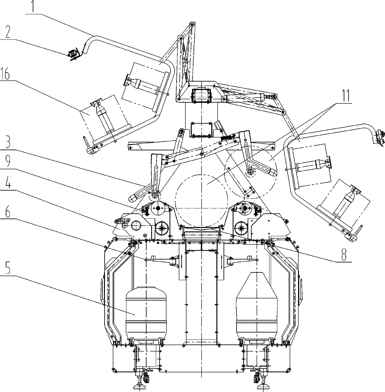
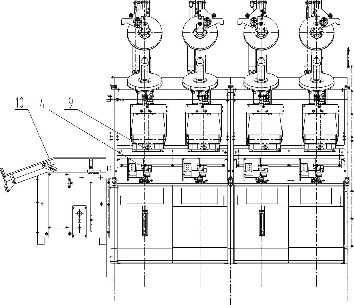
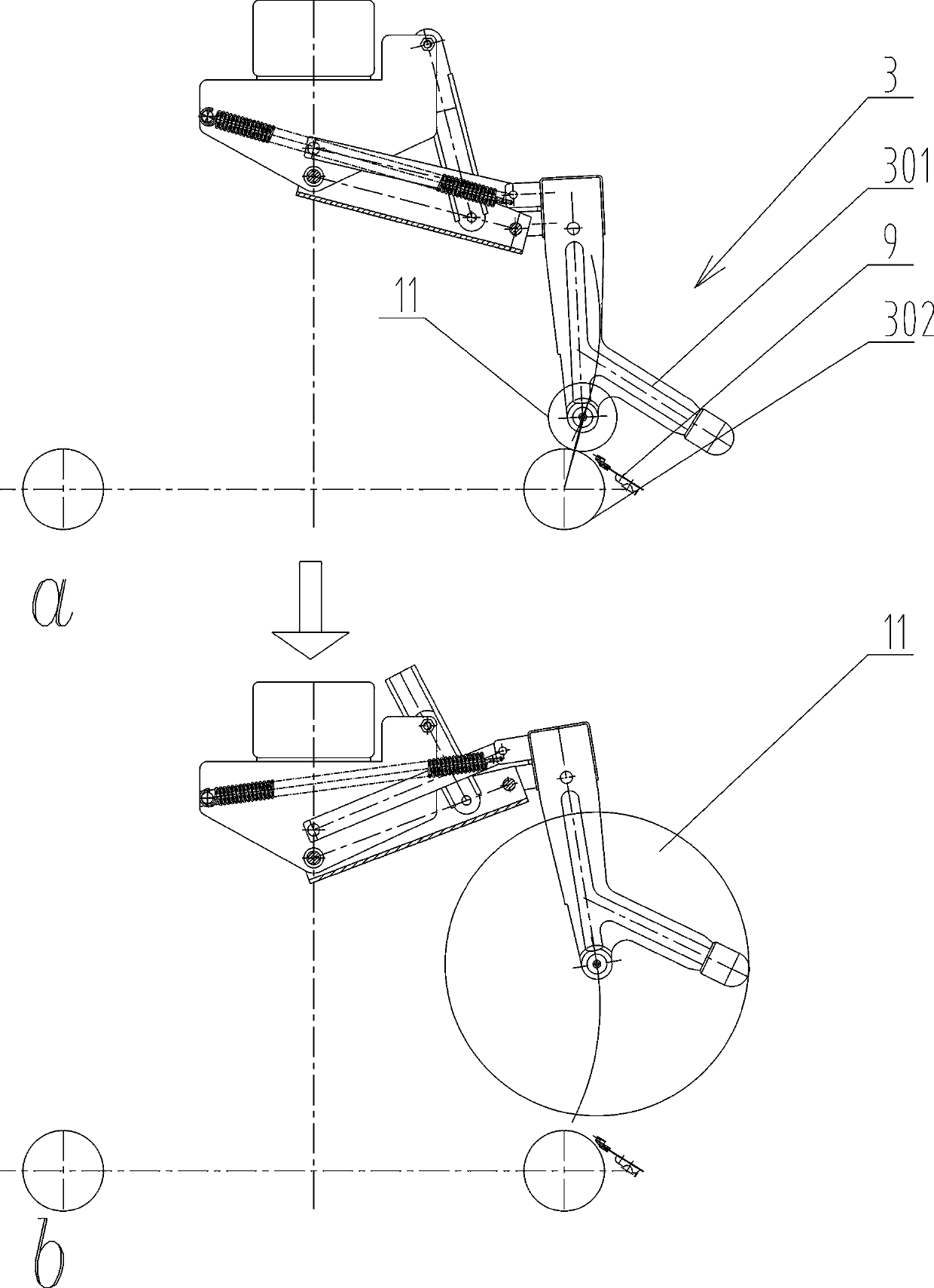
[0045] Such as figure 1 , 2 , 4 to 6, a carpet yarn twisting machine, comprising a frame, a creel device 1, an electric spindle device 5, an overfeeding device 4 and a coiling device 3, in the electric spindle device 5, the hollow spindle bar 502 is fixedly connected with the motor 501. In this example, a synchronous motor is preferably used, and the hollow spindle bar 502 is driven by the motor 501 to rotate. The center of the hollow spindle bar 502 is provided with a yarn path for the outer yarn to pass through, a twisting disc 506 and a yarn storage The disc 505 is fixedly connected with the hollow spindle bar 502 and rotates with the moving hollow spindle bar 502;

[0046] The yarn storage tray 505 is provided with a yarn outlet hole 504 communicating with the inner yarn path of the hollow spindle bar 502 for passing the outer yarn 13 out;

[0047] The spindle pot for accommodating the inner yarn package 15 is connected with the hollow spindle rod 502 through the spindle...


PUM


Abstract

The disclosure describes a yarn twisting machine in which a hollow spindle rod is fixedly connected with a motor that drives the hollow spindle rod to rotate, a twisting disc and a yarn storage disc are fixedly connected with the hollow spindle rod and rotate along with the hollow spindle rod, the yarn storage disc is provided with yarn outlets, which communicate with inner yarn channels of the hollow spindle rod spindle tanks for accommodating inner yarn packages are connected with the hollow spindle rod through spindle rod bearings, and the spindle tanks are immobile.

Description

technical field [0001] The invention relates to the field of textile machinery, in particular to a carpet yarn twisting machine. Background technique [0002] The spindle of the known BCF twisting machine is the spindle tape transmission mode: the main motor in the head box drives the spindle transmission shaft, and the spindle transmission shaft drives the spindle to rotate through the spindle tape. Spindle speed changes are accomplished by changing pulleys. The spindle belt transmission method has problems such as troublesome changing of the spindle speed, heavy workload, large difference in spindle speed between different spindles, and difficult cleaning and maintenance due to occupied space under the spindles. For example the two-for-one twisting spindle described in CN1473077A. Or the two-for-one twisting spindle or the twisting spindle described in CN 102212903 A. In the spindle belt transmission mode, the rotation speed of the spindle rod is usually 3000~6000 rpm, ...

Claims


Application Information

Patent Timeline
Patent Type & Authority Patents(China)
IPC IPC(8): D01H1/08D01H1/10D01H1/20D01H1/244D01H1/36D01H13/10D01H13/16
CPCD01H1/08D01H1/106D01H1/20D01H1/244D01H1/36D01H13/104D01H13/1616D01H7/86D01H7/866D01H7/868D02G3/285D01H1/02D01H13/02D01H13/10
Inventor 杨华明张明许金甲汪斌杨华年刘娅娥陈文涛陆国兴江海波张焕军宋虎李琪
Owner YICHANG JINGWEI TEXTILE MACHINERY
Learn More