Supercharge Your Innovation With Domain-Expert AI Agents!

Deduster equipment

A dust collector and equipment technology, applied in chemical instruments and methods, electrical components, coupling devices, etc., can solve the problems that the touch head cannot be automatically ejected, the power supply connection is unstable, and a large force is applied, so as to achieve locking and unlocking operations Simple and convenient, simple and convenient locking operation, safe and stable power supply effect

Inactive Publication Date: 2017-11-03
苏州玛斯堡威电子科技有限公司
View PDF0 Cites 0 Cited by
  • Summary
  • Abstract
  • Description
  • Claims
  • Application Information

AI Technical Summary

Problems solved by technology

[0002] At present, the electrification of the dust collector is mainly to insert the contact head connected to the dust collector directly into the power transmission port of the power transmission terminal body. Although this cooperation method is simple to operate, the contact head can still be directly inserted into the power transmission port. If it is pulled out, when it accidentally kicks and hits the cable connected between the touch head and the dust collector, it will cause the touch head to be separated from the power transmission port, resulting in a sudden power failure of the dust collector. Therefore, the existing cooperation There is a risk of unstable power supply connection in this method, which may easily cause damage to the dust collector due to sudden power failure. Moreover, the contact head in the existing cooperation method cannot automatically pop up, and a large force needs to be applied when the contact head is pulled out, which is laborious to pull out.

Method used


Image

  • Deduster equipment
  • Deduster equipment
  • Deduster equipment

Examples


Embodiment Construction

[0019] The preferred embodiments of the present invention will be described in detail below in conjunction with the accompanying drawings, so that the advantages and features of the present invention can be more easily understood by those skilled in the art, so as to define the protection scope of the present invention more clearly.

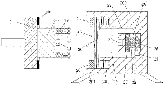
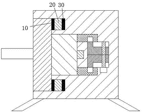
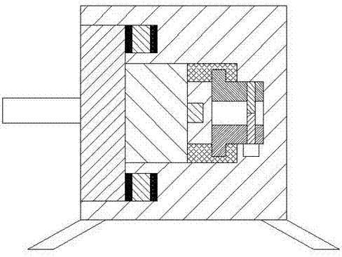
[0020] refer to Figure 1-4 The shown dust collector equipment includes a head for power transmission and a power transmission end body. The head for power transmission includes a first plug-in block 1 and a second plug-in block 11, and the second plug-in block 11 is set In the center of the right end face of the first mating block 1, a touch head 14 is provided at the center of the right end face of the second mating block 11, and two opposite ends of the right end face of the second mating block 11 are arranged respectively. Two connecting strips 12, two locking grooves 13 are respectively arranged on the inner end surfaces of the two connectin...


PUM


Abstract

The invention discloses a dust remover device, which comprises a power transmission head and a power transmission terminal body, the power transmission head includes a first plug-in block and a second plug-in block, and the second plug-in block is arranged on the The center of the right end face of the first plug-in block, the center of the right end face of the second plug-in block is provided with a touch head, and the front and rear ends of the right end face of the second plug-in block are respectively oppositely provided with two connecting bars. Two lock grooves are oppositely arranged on the inner end surface of the connecting bar, and a disc is arranged on the right end surface of the first insertion block, which is located outside the second insertion block, and the power transmission end body Including the shell, the present invention has simple structure, good power supply stability, safe and reliable operation of the whole device, and reasonable structural design. The locking and unlocking operation of the touch head is simple and convenient without being connected with the power transmission port, and is suitable for popularization and use.

Description

technical field [0001] The invention relates to the field of dust collectors, in particular to dust collector equipment. Background technique [0002] At present, the electrification of the dust collector is mainly to insert the contact head connected to the dust collector directly into the power transmission port of the power transmission terminal body. Although this cooperation method is simple to operate, the contact head can still be directly inserted into the power transmission port. If it is pulled out, when it accidentally kicks and hits the cable connected between the touch head and the dust collector, it will cause the touch head to be separated from the power transmission port, resulting in a sudden power failure of the dust collector. Therefore, the existing cooperation There is a risk of unstable power supply connection in this method, which may easily cause damage to the dust collector due to sudden power failure. Moreover, the contact head in the existing coope...

Claims


Application Information

Patent Timeline
IPC IPC(8): B08B13/00H01R4/50H01R13/629
CPCB08B13/00H01R4/5083H01R13/629
Inventor 舒丽燕
Owner 苏州玛斯堡威电子科技有限公司
Features
  • R&D
  • Intellectual Property
  • Life Sciences
  • Materials
  • Tech Scout
  • Unparalleled Data Quality
  • Higher Quality Content
  • 60% Fewer Hallucinations
Learn More