Guiding assembly and bag-open technology using guiding assembly

A technology for guiding components and guiding strips, applied in sewing machine components, textiles and papermaking, sewing equipment, etc., can solve problems such as affecting aesthetics, and achieve the effects of improving production efficiency, maintaining smooth lines, and improving aesthetics.

Inactive Publication Date: 2017-11-03
平湖市龙跃制衣股份有限公司
View PDF5 Cites 0 Cited by
  • Summary
  • Abstract
  • Description
  • Claims
  • Application Information

AI Technical Summary

Problems solved by technology

[0003] When using this method of opening bags, the worker uses the method of visual inspection to aim and cut out the second slit on the bottom material, which is easy to cut

Method used


Image

  • Guiding assembly and bag-open technology using guiding assembly
  • Guiding assembly and bag-open technology using guiding assembly
  • Guiding assembly and bag-open technology using guiding assembly

Examples


Embodiment 1

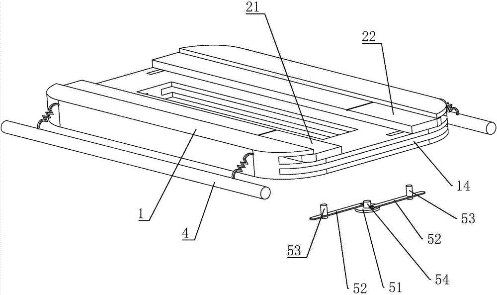
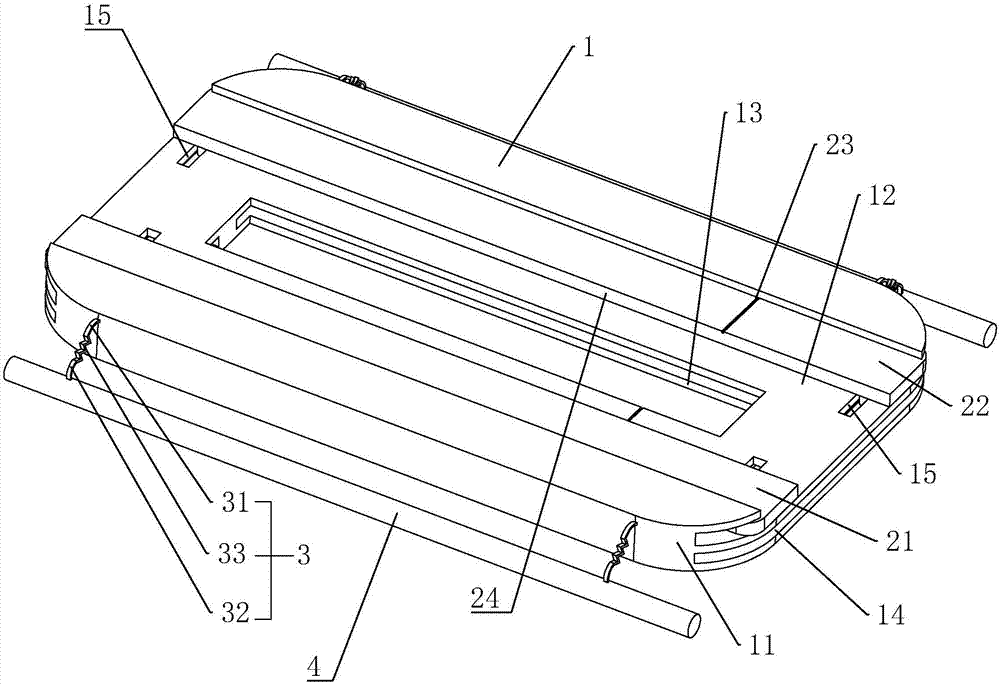
[0048] Embodiment 1: A kind of guiding component, such as figure 1 and figure 2 As shown, the guide plate 1 is included, and the guide plate 1 is elongated, and arc-shaped surfaces 11 are provided on both sides of the guide plate 1 in the width direction.

[0049] A placement groove 12 is provided on the guide plate 1 along its length direction, and a first guide strip 21 and a second guide strip 22 are placed in the placement groove 12, and the first guide strip and the second guide strip 22 are long plates. shape, and the length direction is parallel to the longitudinal direction of the placement groove 12 and the guide plate 1; the width direction is parallel to the width direction of the placement groove 12 and the guide plate 1. The upper and lower surfaces of the first guide bar 21 and the second guide bar 22 are both in contact with the inner wall of the placement groove 12 .

[0050] In order to enable the first guide bar 21 and the second guide bar 22 to move simul...

Embodiment 2

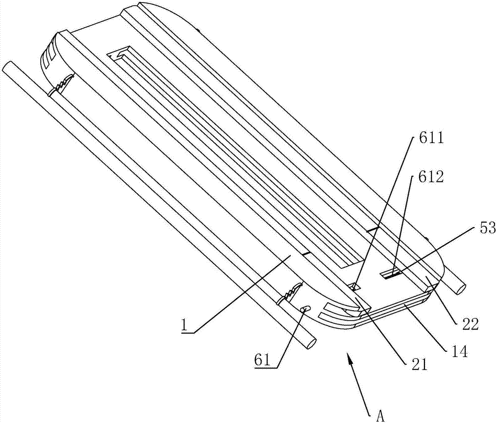
[0056] Embodiment 2: A boot component, such as Figure 3 to Figure 5 As shown, the difference with embodiment 1 is that the linkage plate 51 is removed (see figure 2 )setting.

[0057] Through a strip-shaped threaded mandrel 61 on the guide plate 1, the threaded mandrel 61 is provided with a total of two reverse threads of the first thread 611 and the second thread 612, and one end of the threaded mandrel 61 passes through the guide plate 1. The other end is placed in the installation groove 14 and connected with the inner wall of the installation groove 14 through the bearing 64 .

[0058] The first thread 611 is sleeved and threaded with a first guide sleeve 62 , the second thread 612 is sleeved and threaded with a second guide sleeve 63 , and the first guide sleeve 62 is fixed to the first guide bar 21 through the guide post 53 The second guide sleeve 63 is fixedly connected with the second guide bar 22 through the guide post 53 .

[0059] When in use, by rotating the s...

Embodiment 3

[0060] Embodiment 3: a kind of boot assembly, such as Figure 6 to Figure 8 As shown, the difference with embodiment 1 is that the linkage plate 51 is removed (see figure 2 )setting.

[0061] The first gear 71 and the second gear 72 meshed with each other are connected by rotation in the installation groove 14 , and the radii of the first gear 71 and the second gear 72 are equal. The first gear 71 meshes with the first rack 73, the second gear 72 meshes with the second rack 74, and the first rack 73 and the second rack 74 are arranged in an L shape; the first rack 73 passes through the guide groove 15 and is fixedly connected with the lower surface of the first guide bar 21 , the second rack 74 passes through the guide groove 15 and is fixedly connected with the lower surface of the second guide bar 22 .

[0062] A guide rod 75 is fixed in the guide groove 15, and the guide rod 75 passes through the first rack 73 and the second rack 74. The length direction of the guide rod...


PUM


Abstract

The invention discloses a guiding assembly. The problem of unattractiveness caused when a pocket is opened, since a first gap on pocket cloth and a second gap on bottom fabric are not parallel is solved. According to the technical scheme, the guiding assembly is characterized by comprising a guiding plate used for being arranged to abut against the surface of the bottom fabric, the guiding plate is provided with a placing groove, a through groove used for placing a presser foot of a sewing machine is formed in the bottom wall of the placing groove, the placing groove is internally provided with a first guiding strip and a second guiding strip, the first guiding strip and the second guiding strip are arranged at the two sides of the through groove respectively, an accommodating groove used for placing the pocket cloth is formed between the first guiding strip and the second guiding strip, and the through groove, the placing groove, the first guiding strip and the second guiding strip are mutually parallel in the length directions, so that the first gap and second gap are parallel, and the purpose of attractiveness is achieved.

Description

technical field [0001] The invention relates to the field of bag opening for clothes, more specifically, it relates to a guide assembly and a bag opening process using the guide assembly. Background technique [0002] At present, it is necessary to open the bag before sewing the clothes pocket, and the following steps are used to open the bag: first, cut the pocket cloth into two symmetrical strips along the length direction of the pocket cloth with scissors; , spread the base material on the workbench of the sewing machine, arrange the two sections of cloth strips in parallel along the length direction and spread them on the base material, so that the first gap is formed between the two sections of cloth strips; thirdly, start the sewing machine, Sew these two sections of cloth strips on the bottom material; thirdly, cut the bottom material along the first gap with scissors, and cut out the second gap on the bottom material. [0003] When using this method of opening bags,...

Claims


Application Information

Patent Timeline
IPC IPC(8): D05B35/06D05B35/12
CPCD05B35/066D05B35/12
Inventor 蒋海良
Owner 平湖市龙跃制衣股份有限公司
Why Eureka
Try Eureka