
A superimposed rotating electromagnet with a curved surface rotating shaft

A technology for rotating electromagnets and rotating shafts, which is applied in the directions of electromagnets and electromagnets without armatures, can solve problems such as being unsuitable for cylinder control and detection processes.

Active Publication Date: 2018-12-14
GUANGZHOU WAYTOP ELECTRONICS
View PDF7 Cites 0 Cited by
  • Summary
  • Abstract
  • Description
  • Claims
  • Application Information

AI Technical Summary

Problems solved by technology

[0002] In the flaw detection process of the iron and steel industry, because the round steel needs to be detected online during production, the flaw detection mechanism needs to realize the tight detection during the operation of the steel, and release the mechanism when there is no steel; this kind of flaw detection mechanism needs to provide more Large torque, and in a high temperature environment, it is not suitable to use the cylinder for the control and detection process

Method used


Image

  • A superimposed rotating electromagnet with a curved surface rotating shaft
  • A superimposed rotating electromagnet with a curved surface rotating shaft
  • A superimposed rotating electromagnet with a curved surface rotating shaft

Examples


Embodiment Construction

[0027] Now the present invention is further described in conjunction with description of drawings and embodiments:

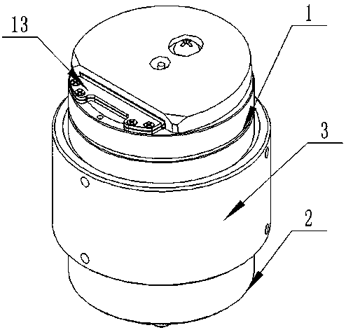
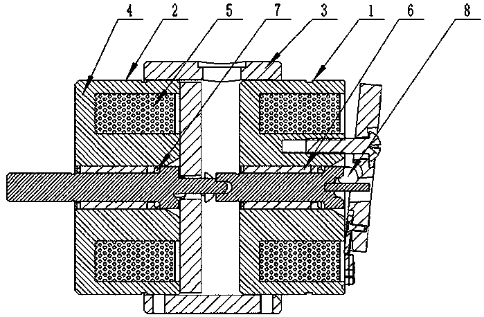
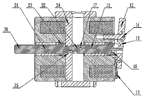
[0028] refer to Figures 1 to 8 , a superimposed rotating electromagnet with a curved surface rotating shaft, where:

[0029] Including the main rotating electromagnet 1: the main rotating electromagnet 1 has a yoke 4, a coil 5, a main shaft 11, a cover plate 12 and a universal ball 8; the yoke 4 has a hollow central column 41 and a concentric outer wall 42, and the hollow central column 41 and The bottom end of the concentric outer wall 42 is closed to form an annular groove 43, and the coil 5 is wound in the groove 43; the hollow of the hollow center column 41 is provided with a bearing 6; one end of the cover plate 12 is provided with a spring piece 13, and the other end is opened There is a fixing hole 19, a central circular hole 18 is provided in the middle, and a cover plate curved sliding groove 15 is provided on the edge of the central circular hole 18....


PUM


Abstract

A curved-surface rotation axis superposed rotation electromagnet comprises a main rotation electromagnet, wherein the main rotation electromagnet comprises a yoke, coils, a main shaft, a cover plate and an universal ball, a bearing is fixedly arranged in the center of the yoke, the main shaft is arranged on the bearing, one end of the main shaft penetrates through a bottom end of the yoke and is provided with an engagement bayonet, the other end of the main shaft extends to a central round hole of the cover plate, a main shaft curved-surface sliding groove is formed in the main shaft at a lower side of the cover plate, a cover plate curved-surface sliding groove is formed in one side, near to the yoke, of the cover plate, the cover plate curved-surface sliding groove and the main shaft curved-surface sliding groove are matched to form a limitation groove, the universal ball is arranged in the limitation groove, and the main shaft curved-shaft sliding groove is an irregularly-shaped curved-shaft sliding groove of which the curvature of a curved surface is gradually changed. By the curved-surface rotation axis superposed rotation electromagnet, a large torque is provided, and flaw detection and check can be accurately performed on a steel material in a high-temperature temperature; and after the electromagnets in two different working directions are combined, the detection mechanism is automatically opened and closed by circuit control.

Description

technical field [0001] The invention relates to the field of non-destructive testing, in particular to a superimposed rotating electromagnet with curved rotating shafts. Background technique [0002] In the flaw detection process of the iron and steel industry, because the round steel needs to be detected online during production, the flaw detection mechanism needs to realize the tight detection during the operation of the steel, and release the mechanism when there is no steel; this kind of flaw detection mechanism needs to provide more Large torque, and in a high temperature environment, it is not suitable to use the cylinder for the control and detection process. Contents of the invention [0003] In order to overcome the above-mentioned shortcomings of the prior art, the purpose of the present invention is to provide a curved rotating shaft superimposed rotating electromagnet with a large torque and which can work in a high temperature environment. [0004] The techni...

Claims


Application Information

Patent Timeline
Patent Type & Authority Patents(China)
IPC IPC(8): H01F7/20
CPCH01F7/20
Inventor 陈晓鸣
Owner GUANGZHOU WAYTOP ELECTRONICS
Learn More