Indoor ceiling lamp mounting structure

A technology of installation structure and inner ceiling lamp, which is applied to lighting devices, fixed lighting devices, lighting auxiliary devices, etc., can solve the problems of unstable installation of lamps, loose fastening bolts, easy to smash people, etc., and achieve convenient cleaning or maintenance. Simple installation and removal process, stable power supply

Inactive Publication Date: 2017-11-07
佛山驰博科技有限公司
View PDF3 Cites 0 Cited by
  • Summary
  • Abstract
  • Description
  • Claims
  • Application Information

AI Technical Summary

Problems solved by technology

[0002] Indoor lighting is generally installed on the ceiling, because it is installed at a high place, a ladder or other climbing equipment is required for installation and removal, but traditional lamps need to drill holes in the ceiling to install the lamp on the ceiling , but punching holes on the ladder has certain risks, and the operation is cumbersome. When the lamp needs to be removed, it is easy to cause loosening of the fastening bolts. Therefore, the installation of the lamp will be unstable. If it falls, it will cause damage to the lamp. easy to hurt people

Method used


Image

  • Indoor ceiling lamp mounting structure
  • Indoor ceiling lamp mounting structure
  • Indoor ceiling lamp mounting structure

Examples


Embodiment Construction

[0015] All features disclosed in this specification, or steps in all methods or processes disclosed, may be combined in any manner, except for mutually exclusive features and / or steps.

[0016] Any feature disclosed in this specification (including any appended claims, abstract and drawings), unless expressly stated otherwise, may be replaced by alternative features which are equivalent or serve a similar purpose. That is, unless expressly stated otherwise, each feature is one example only of a series of equivalent or similar features.

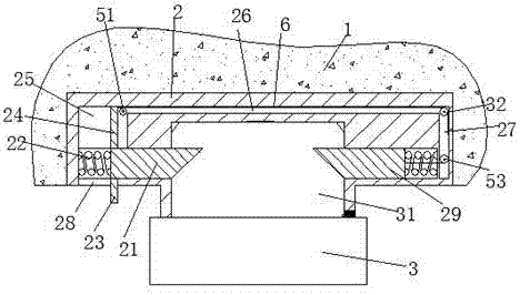
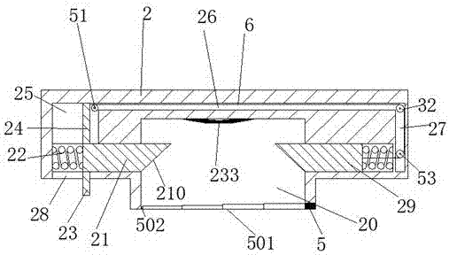
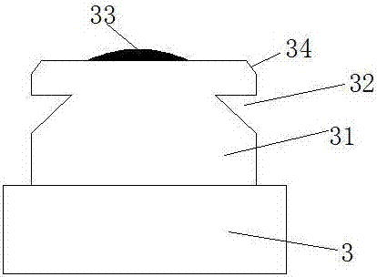
[0017] Such as Figure 1-Figure 4 As shown, an installation structure for an indoor dome light of the present invention includes a fixed housing 2 fixedly installed in the top wall 1 and a lighting fixture 3, the upper end of the lighting fixture 3 is fixedly provided with a mounting head 31, and the mounting head The top of 31 is provided with a conductive protrusion 33, and the two sides of the installation head 31 are also provided with lo...


PUM


Abstract

The invention discloses an indoor ceiling lamp mounting structure which comprises a fixing shell fixedly mounted in the top wall, and an illuminating lamp. A mounting head portion is fixedly arranged at the upper end of the illuminating lamp. An electric conduction protrusion is arranged at the top end of the mounting head portion. Lock grooves are further formed in the two side surfaces of the mounting head portion. A mounting groove matched with the mounting head portion is formed in the center of the fixing shell. An elastic electric conduction plate is mounted on the top wall of the mounting groove. A left sliding groove and a right sliding groove are symmetrically formed in the two sides of the fixing shell correspondingly, and communicate with and are orthogonal to the mounting groove. A left lock pin and a right lock pin are mounted in the left sliding groove and the right sliding groove correspondingly. A compressed spring is mounted between the outer side end of the left lock pin and the inner end wall of the left sliding groove as well as between the outer side end of the right lock pin and the inner end wall of the right sliding groove. The inner side ends of the left lock pin and the right lock pin stretch into the mounting groove. An unlocking device is further mounted in the fixing shell.

Description

technical field [0001] The invention relates to the field of lighting devices, in particular to an installation structure for an indoor dome light. Background technique [0002] Indoor lighting is generally installed on the ceiling, because it is installed at a high place, a ladder or other climbing equipment is required for installation and removal, but traditional lamps need to drill holes in the ceiling to install the lamp on the ceiling , but punching holes on the ladder has certain risks, and the operation is cumbersome. When the lamp needs to be removed, it is easy to cause loosening of the fastening bolts. Therefore, the installation of the lamp will be unstable. If it falls, it will cause damage to the lamp It is easy to hurt people. Contents of the invention [0003] The technical problem to be solved by the present invention is to provide an installation structure for an indoor dome light which is easy to install and remove. [0004] The present invention is ac...

Claims


Application Information

Patent Timeline
IPC IPC(8): F21S8/04F21V21/02
CPCF21S8/04F21V21/02
Inventor 肖小玉
Owner 佛山驰博科技有限公司
Why Eureka
Try Eureka