[0021] In the description of the present invention, it should be understood that the terms "center", "longitudinal", "transverse", "upper", "lower", "front", "rear", "left", "right", " The orientation or positional relationship indicated by "vertical", "horizontal", "top", "bottom", "inner", "outer" etc. is based on the orientation or positional relationship shown in the drawings, and is only for the purpose of describing the present invention And to simplify the description, rather than indicating or implying that the device or element referred to must have a specific orientation, be constructed and operated in a specific orientation, and therefore cannot be understood as a limitation of the present invention. In addition, the terms "first" and "second" are only used for descriptive purposes, and cannot be understood as indicating or implying relative importance or implicitly indicating the number of technical features indicated. Therefore, the definition of "first" and "second" is only for descriptive purposes, and cannot be understood as indicating or implying relative importance or implicitly including one or more of these features. In the description of the present invention, unless otherwise specified, "plurality" means two or more.
[0022] In the description of the present invention, it should also be noted that the terms "set", "installation", "connected", and "connected" should be interpreted broadly, unless otherwise clearly specified and limited. For example, it may be a fixed connection. It can also be detachably connected or integrally connected; it can be mechanically connected or electrically connected; it can be directly connected or indirectly connected through an intermediate medium, and it can be the internal communication between two components. For those of ordinary skill in the art, the specific meanings of the above-mentioned terms in the present invention can be understood in specific situations.
[0023] The technical solutions in the embodiments of the present invention will be clearly and completely described below in conjunction with the accompanying drawings in the embodiments of the present invention. Obviously, the described embodiments are only a part of the embodiments of the present invention, rather than all the embodiments. Based on the embodiments of the present invention, all other embodiments obtained by those of ordinary skill in the art without creative work shall fall within the protection scope of the present invention.
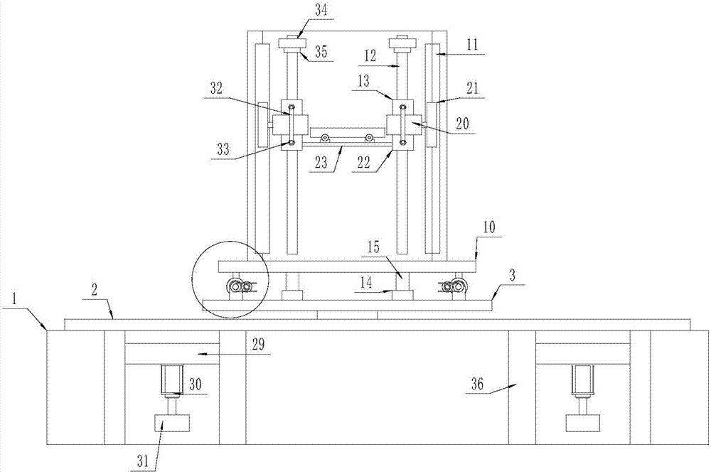
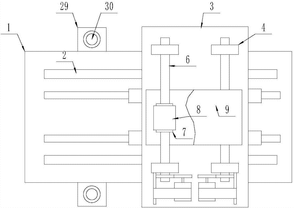
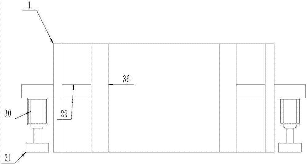
[0024] The present invention provides Figure 1-5 The illustrated material lifting device with auxiliary tightening function and movable in a plane includes a base 1 with a cavity mechanism inside and a rectangular mechanism outside, and a front and rear moving mechanism is provided on the end surface of the base 1 , The forward and backward movement mechanism is provided with a left and right movement mechanism, the left and right movement mechanism is provided with a lifting mechanism, the lifting mechanism is provided with a material tightening mechanism, and the forward and backward moving mechanism is composed of a device installed on the base 1 The rodless cylinder 2, the carrier plate 3 installed at the moving end of the rodless cylinder 2, and the first auxiliary mechanism provided between the carrier plate 3 and the base 1 are jointly constituted, and the forward and backward movement mechanism is installed in the The two pairs of shaft brackets 4 on the carrier plate 3, the bearings 5 embedded in the shaft bracket 4, the lead screws 6 inserted on the left and right opposite bearings 5, and the lead screw pairs 7, which are matched and installed on the lead screws 6, A mounting block 8 fixed on the outer wall of the screw pair 7, a sliding plate 9 fixed on a pair of the mounting blocks 8 and a driving mechanism fixed on the shaft frame 4 are formed together, and the lifting mechanism is installed on the sliding plate 9 The vertical mounting frame 10, a pair of vertical racks 11 mounted on the vertical mounting frame 10, the sliding rail 12 mounted on the mounting frame 10, the sliding member 13 and the fixing mounted on the sliding rail 12 The material placement drive mechanism on the slide 13 is jointly constituted; the first auxiliary mechanism is composed of a pair of slides 14 opened on the end surface of the base 1 and a slide body 15 fitted in the slide 14, The sliding body 15 is fixedly connected to the outer wall of the carrier board 3; the driving mechanism is composed of a motor frame 16 mounted on the outer wall of the shaft frame 4, a first drive member 17 fixed on the motor frame 16, and a first drive member 17 The driving gear 18 at the driving end and the driven gear 19 matched and installed on the end surface of the lead screw 6 are formed together. The driving gear 18 meshes with the driven gear 19; the material placement driving mechanism is driven by the sliding member 13 The box 22, the second driving member 20 installed inside the driving box 22, the gear 21 fitted on the driving end of the second driving member 20, and the material placing rack 23 fixed on a pair of opposite walls of the driving box 22 are formed together, so The gear 21 meshes with the rack 11; the material tightening mechanism consists of a pair of sliding grooves 24 opened on the material placing frame 23, a tightening block 25 fitted inside the sliding groove 24, and a first fixed on the tightening block 25 The tightening plate 26, the second tightening plate 27 fixed on the material placing frame 23 and close to one end thereof, and the telescopic motor 28 fixed on the side of the material placing frame 23 are formed together, and the telescopic motor 28 and the first tightening plate The plate 26 is fixedly connected; a second auxiliary mechanism is installed on the outer wall of the base 1, and the second auxiliary mechanism is composed of a supporting plate 29 fitted inside the base 1 and extending outside, and a hydraulic pressure mounted on the supporting plate 29 The cylinder 30 and the support block 31 fitted on the piston end of the hydraulic cylinder 30 are jointly constituted; the sliding member 13 has a solid mechanism inside and a rectangular mechanism outside, and threaded holes are opened on the end surface of the sliding member 13 and close to both sides thereof, so A bolt 33 is installed in the threaded hole, and a fastening frame 32 is fixed on the bolt 33, and the fastening frame 32 is in contact with the end surface of the second driving member 20; the rack 1 1. A limit plate 34 is installed at the lower and upper ends, and a limit switch 35 is installed on the limit plate 34; a plurality of tightening ribs 36 are fixed inside the base 1, and the supporting plate 29 is fixed to the reinforcing rib 36 Connection; The material placement frame 23 and located at its left and right ends are equipped with a plurality of locks 37, and the locks 37 are equipped with fastening belts on the left and right sides.
[0025] The feature of this embodiment is that the base has a cavity mechanism inside and a rectangular mechanism outside. The end of the base is equipped with a forward and backward movement mechanism, the front and rear movement mechanism is equipped with a left and right movement mechanism, and the left and right movement mechanism is equipped with a lifting mechanism. There is a material tightening mechanism. The forward and backward moving mechanism is composed of a pair of rodless cylinders installed on the base, a carrier plate mounted on the moving end of the rodless cylinder, and a first auxiliary mechanism set between the carrier plate and the base. The forward and backward moving mechanism is composed of two pairs of shaft brackets mounted on the carrier plate, bearings embedded in the shaft bracket, lead screws inserted on the left and right opposite bearings, and screw pairs mounted on the lead screws. The mounting block fixed on the outer wall of the lead screw, the sliding plate fixed on a pair of mounting blocks and the driving mechanism fixed on the shaft frame are composed of a vertical mounting frame mounted on the sliding plate and a vertical mounting frame. A pair of vertical racks on the mounting frame, a sliding rail mounted on the mounting frame, a sliding member mounted on the sliding rail and a material placement driving mechanism fixed on the sliding member are jointly constituted. This technical solution has The three-way moving mechanism can fully realize the front, rear, left, and right moving mechanism, which is very convenient. At the same time, while lifting the material, the material can also be tightened by the tightening device without manual guards, reducing manual work pressure.
[0026] In this embodiment, first install a PLC series controller in the free place of the device, and connect the series of controllers to the terminals of each power software in the device through the personnel in the field, which is convenient for manual operation. The controller controls the piston end of the hydraulic cylinder 30 to push the support block 31 into contact with the ground to complete the preliminary fastening, which makes the overall device more stable. The hydraulic cylinder 30 is stably supported by the tightening rib 36 and the support plate 29 inside the abutment 1. Control the moving ends of a pair of rodless cylinders 2 to move the carrier plate 3 to the loading position, and support the carrier plate 3 through the cooperation of the slide 14 and the sliding body 15, and at the same time control the first driving motor to drive the driving gear 18 After the driving gear 18 meshes with the driven gear 19, the lead screw 6 on the pedestal 4 rotates, then the lead screw pair 7 on the lead screw 6 rotates, and the lead screw pair 7 moves forward and backward with the sliding plate 9 to accurately Adjust the position of the material placement frame 23 and control the second driving member 20 on the mounting frame 10 to drive the gear 21, the gear 21 and the rack 11, since the rack 11 is fixed on the mounting frame 10, and the second driving member 20 is fixed to the sliding member 13. The sliding member 13 fixes the second driving member 20 on the sliding member 13 through the bolt 33 and the fastening bracket 32, so the sliding member 13 can move up and down with the material placing rack 23. Manually place the material on the material placing rack 23, push the tightening block 25 to move in the chute 24 by the telescopic motor 28, move the first tightening plate 26 on the tightening block 25 close to the second tightening plate 27, tighten the material, and pass The cooperation of the fastening belt and the lock buckle 37 completely tighten the material, and then lift the material through the above working principle.
[0027] Finally, it should be noted that the above are only the preferred embodiments of the present invention and are not intended to limit the present invention. Although the present invention has been described in detail with reference to the foregoing embodiments, it is still for those skilled in the art. The technical solutions described in the foregoing embodiments can be modified, or some of the technical features can be equivalently replaced. Any modification, equivalent replacement, improvement, etc., made within the spirit and principle of the present invention shall be included in Within the protection scope of the present invention.