
Mobile terminal compatible with built-in and external antennae

A technology of external antennas and internal antennas, applied in antennas, antenna components, diversity/multi-antenna systems, etc., can solve the problems of MIMO functional performance, small antenna clearance area, and increase network speed, etc., to achieve improvement The effect of data download rate, improved antenna performance, and increased throughput

Inactive Publication Date: 2017-11-14
GUANGDONG OPPO MOBILE TELECOMM CORP LTD
View PDF11 Cites 16 Cited by
  • Summary
  • Abstract
  • Description
  • Claims
  • Application Information

AI Technical Summary

Problems solved by technology

However, although the MIMO (Multiple-Input Multiple-Output) function design scheme of the built-in antenna in the mobile terminal has improved the ability of the mobile terminal to receive and transmit signals to a certain extent, it has not achieved the maximum improvement. internet speed
For example, when a user watches a video through a mobile terminal, he hopes to obtain a higher network speed. However, due to the contradiction between the high network speed and the small clearance area of ​​the built-in antenna of the mobile terminal, the network speed for the antenna to download data from the base station is limited.
As a result, the performance of the MIMO (function) of the mobile terminal is not good, the practicability is not strong, and it cannot meet the requirements of maximizing network speed.
For example, outdoors, users need to use mobile terminals to watch live video, etc., because the performance of the MIMO function of the mobile terminal cannot be improved, and the 4×4 MIMO and multi-band carrier aggregation capabilities of the base station cannot be fully utilized, resulting in freezes in the live video Phenomena that affect the playback effect

Method used


Image

  • Mobile terminal compatible with built-in and external antennae
  • Mobile terminal compatible with built-in and external antennae
  • Mobile terminal compatible with built-in and external antennae

Examples


Embodiment Construction

[0025] The present invention will be further described in detail below in conjunction with the accompanying drawings and embodiments. It should be understood that the specific embodiments described here are only used to explain the present invention, but not to limit the present invention. In addition, it should be noted that, for the convenience of description, only some structures related to the present invention are shown in the drawings but not all structures.

[0026] Before discussing the exemplary embodiments in more detail, it should be mentioned that some exemplary embodiments are described as processes or methods depicted as flowcharts. Although the flowcharts describe the steps as sequential processing, many of the steps may be performed in parallel, concurrently, or simultaneously. Additionally, the order of steps may be rearranged. The process may be terminated when its operations are complete, but may also have additional steps not included in the figure. The ...


PUM


Abstract

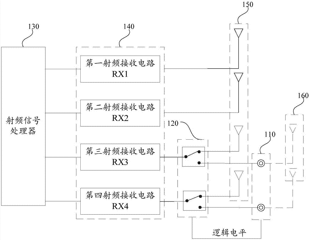
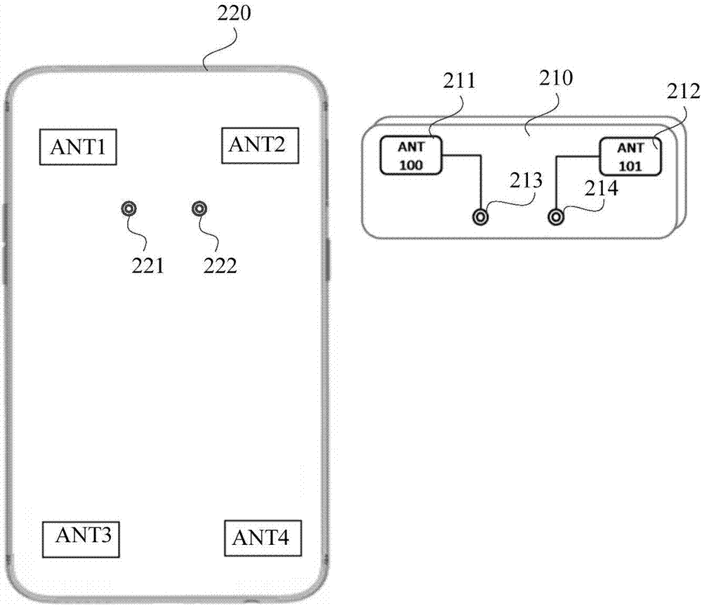
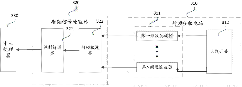
An embodiment of the invention discloses a mobile terminal compatible with built-in and external antennae. The mobile terminal comprises an external antenna connecting port and an antenna switching circuit. The external antenna connecting port comprises a detecting pin and a signal receiving pin for connection of an external antenna device. Furthermore when the external antenna device is connected with the external antenna connecting port, the logical level of the detecting pin is overturned, and the signal receiving pin is electrically connected with the signal pin of the external antenna device. The antenna switching circuit is electrically connected with a built-in antenna, an RF receiving circuit, the detecting pin and the signal receiving pin, and is used for connecting the RF receiving circuit with the built-in antenna or connecting the RF receiving circuit with the external antenna device according to the logical level. The mobile terminal realizes replacement of the built-in antenna by the external antenna for communication after the external antenna device is connected, thereby settling a problem of downloading rate reduction caused by limited MIMO function of the built-in antenna, improving antenna performance, and improving data throughput.

Description

technical field [0001] The embodiments of the present invention relate to a mobile terminal, in particular to a mobile terminal compatible with built-in and external antennas. Background technique [0002] When a user uses a mobile terminal to make calls, send text messages, play online games, and forward microblogs, the relevant data is transmitted and received in the form of radio frequency signals through the antenna. [0003] As consumers have higher requirements for the appearance of mobile terminals, their profiles have become thinner and their display screens have become larger. At the same time, in order to make the appearance more beautiful, the antenna is also changed from external to internal. However, although the MIMO (Multiple-Input Multiple-Output) function design scheme of the built-in antenna in the mobile terminal has improved the ability of the mobile terminal to receive and transmit signals to a certain extent, it has not achieved the maximum improvement...

Claims


Application Information

Patent Timeline
IPC IPC(8): H04B7/0413H04B7/06H01Q1/24
CPCH01Q1/241H04B7/0413H04B7/0602
Inventor 杨金胜
Owner GUANGDONG OPPO MOBILE TELECOMM CORP LTD
Learn More