Exhaust components and compressors

A technology for compressors and components, applied in the field of compressors, can solve the problems of high exhaust oil content, inability to install, and the oil separation structure occupies a large space, and achieve the effects of reducing exhaust oil content, improving energy efficiency, and increasing the amount of compressed refrigerant.

Active Publication Date: 2020-12-25
GREE ELECTRIC APPLIANCES INC
View PDF5 Cites 0 Cited by
  • Summary
  • Abstract
  • Description
  • Claims
  • Application Information

AI Technical Summary

Problems solved by technology

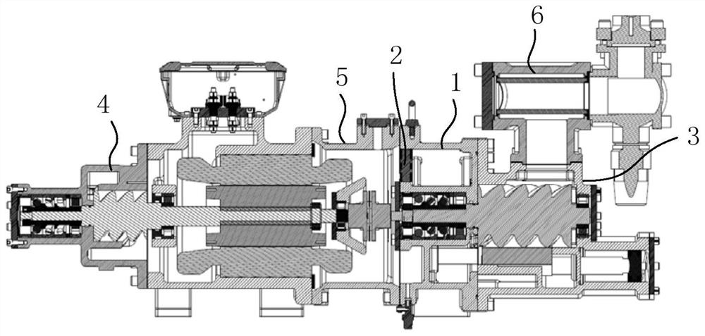
[0005] The purpose of the present invention is to propose an exhaust assembly and compressor, which can solve the problem that the exhaust gas contains too much oil, and the oil separation structure occupies a large space, and cannot be installed due to space constraints.

Method used


Image

  • Exhaust components and compressors
  • Exhaust components and compressors
  • Exhaust components and compressors

Examples


Embodiment Construction

[0033] The technical solutions in the embodiments of the present invention will be clearly and completely described below in conjunction with the drawings in the embodiments of the present invention. Apparently, the described embodiments are only some of the embodiments of the present invention, not all of them. Based on the embodiments of the present invention, all other embodiments obtained by persons of ordinary skill in the art without creative efforts fall within the protection scope of the present invention.

[0034] In describing the present invention, it is to be understood that the terms "central", "longitudinal", "transverse", "front", "rear", "left", "right", "vertical", "horizontal", The orientations or positional relationships indicated by "top", "bottom", "inner", "outer", etc. are based on the orientations or positional relationships shown in the drawings, and are only for the convenience of describing the present invention and simplifying the description, rathe...


PUM


Abstract

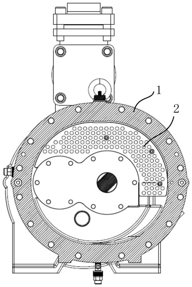
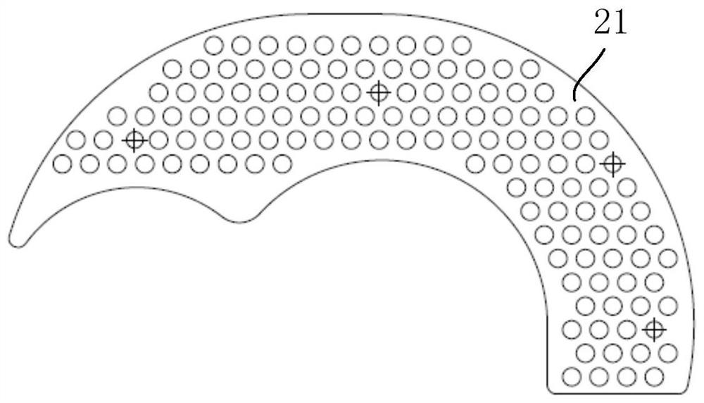
The invention relates to an exhaust assembly and a compressor, wherein the exhaust assembly includes an exhaust bearing seat, the air intake end of the exhaust bearing seat is provided with an air intake cavity, and the exhaust end of the exhaust bearing seat is provided with There is an exhaust cavity, the air intake cavity and the exhaust cavity are staggered along the axial direction of the exhaust bearing seat, and the exhaust bearing seat is provided with a connection between the air intake cavity and the exhaust cavity The flow channel, the oil separation structure is arranged in the exhaust cavity. In the embodiment of the present invention, the intake cavity and the exhaust cavity are staggered along the axial direction of the exhaust bearing seat, and the exhaust of the intake cavity is led to the exhaust cavity by setting a flow channel, and an oil separation structure is arranged in the exhaust cavity. It can make full use of the space at the exhaust end of the exhaust bearing seat and install the oil separation structure, which solves the problem that the oil separation structure occupies a large space in the prior art and cannot be installed due to space constraints; moreover, by setting the oil separation structure, the oil content of the exhaust gas can be significantly increased The amount of effective compressed refrigerant increases, and the energy efficiency is significantly improved.

Description

technical field [0001] The invention relates to the technical field of compressors, in particular to an exhaust assembly and a compressor. Background technique [0002] In a single-unit two-stage screw compressor, the first-stage exhaust gas cools the motor and then enters the second-stage compression chamber. In order to reduce the temperature and lubricate the bearing, it is necessary to inject refrigerated oil into the bearing chamber, and the refrigerated oil in the bearing chamber will eventually return to the second stage. In the rotor cavity of the stage, it flows out with the exhaust gas. For conventional single-stage screw compressors, there is only one stage of rotor, and the amount of refrigerated oil returned to the rotor cavity is not large. Most of the refrigerated oil can be filtered out through the built-in oil separation structure, which has little impact on energy efficiency. [0003] For a single-unit two-stage screw compressor, there is not only the retu...

Claims


Application Information

Patent Timeline
Patent Type & Authority Patents(China)
IPC IPC(8): F04C29/12F04C29/02
CPCF04C29/0092F04C29/026F04C29/12F04C18/16F04C29/06F04C29/02
Inventor 曹聪张天翼毕雨时
Owner GREE ELECTRIC APPLIANCES INC
Why Eureka
Try Eureka