Suction pipeline with oil-gas separation function and parallel compressor unit

A compressor unit and suction pipeline technology, applied in the field of compressors, can solve the problems of compressor oil shortage failure, high air velocity, etc., achieve the effect of reducing the oil content in the exhaust gas and ensuring reliable operation

Active Publication Date: 2021-09-21
TRANE AIR CONDITIONING SYST (CHINA) CO LTD
View PDF5 Cites 0 Cited by
  • Summary
  • Abstract
  • Description
  • Claims
  • Application Information

AI Technical Summary

Problems solved by technology

When the parallel compressor unit operates under high flow conditions, the oil cannot flow back to the oil pool at the lower part of the compressor due to the high velocity of the upward airflow, and the oil level of the operating compressor will continue to be kept at a low oil level, which is easy The risk of compressor failure due to lack of oil

Method used


Image

  • Suction pipeline with oil-gas separation function and parallel compressor unit
  • Suction pipeline with oil-gas separation function and parallel compressor unit
  • Suction pipeline with oil-gas separation function and parallel compressor unit

Examples


Embodiment Construction

[0021] Reference will now be made in detail to the exemplary embodiments, examples of which are illustrated in the accompanying drawings. When the following description refers to the accompanying drawings, the same numerals in different drawings refer to the same or similar elements unless otherwise indicated. The implementations described in the following exemplary examples do not represent all implementations consistent with the present invention. Rather, they are merely examples of apparatuses and methods consistent with aspects of the invention as recited in the appended claims.

[0022] The suction pipeline with oil-gas separation function and the parallel compressor unit with it according to an embodiment of the present invention will be described in detail below with reference to the accompanying drawings.

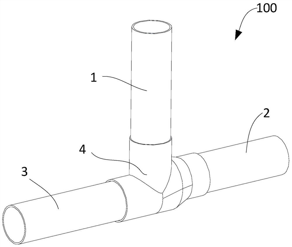
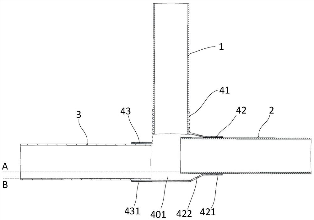
[0023] see figure 1 , the suction pipeline 100 with oil-gas separation function according to an embodiment of the present invention includes a three-way pipe 4 an...


PUM


Abstract

The invention provides a suction pipeline and a parallel compressor unit with the oil-gas separation function. Wherein, the suction pipeline with oil-gas separation function includes a three-way pipe and an air intake main pipe, a first air intake branch pipe, and a second air intake branch pipe respectively connected with the three-way pipe, and the three-way pipe is inside the An oil collection space is formed between the first air intake branch pipe and the second air intake branch pipe, and the communication position between the oil collection space and the first air intake branch pipe is higher than that between the oil collection space and the second air intake branch pipe. The connection position of the intake branch pipe, so that the separated oil enters the second intake branch pipe, and the separated gas enters the first intake branch pipe to realize the separation of oil and gas. The suction pipeline with oil-gas separation function provided by the present invention can realize oil-gas separation and avoid the reverse flow direction of oil and part of the air flow, and its application in compressor units can reduce the exhaust oil content of compressor units , to ensure the reliable operation of the compressor.

Description

technical field [0001] The invention relates to the technical field of compressors, in particular to an air suction pipeline and a parallel compressor unit with an oil-gas separation function. Background technique [0002] The parallel compressor unit includes two compressors, the suction chambers of the two compressors are connected through a tee, and the lower parts of the two compressors are connected through an oil balance pipe. When a single compressor in a parallel compressor train is running, the running compressor will suck most of the gas and oil. A small portion of the gas will enter the non-operating compressor, pass through the gap between the motor stator and the compressor housing of the non-operating compressor and the gap between the motor stator and the motor rotor, and enter the running compressor through the oil balance pipe bottom of the compressor. This part of the gas will go up through the gap between the motor stator and the compressor housing of th...

Claims


Application Information

Patent Timeline
Patent Type & Authority Patents(China)
IPC IPC(8): F25B43/00F25B41/40F25B6/02
CPCF25B43/00F25B41/00F25B6/02
Inventor 欧阳军何佳明张龙孙兵
Owner TRANE AIR CONDITIONING SYST (CHINA) CO LTD
Why Eureka
Try Eureka