
Support structure and compressor with same

A support structure and compressor technology, which is applied in the field of compressors, can solve the problems of high exhaust oil discharge rate, achieve the effects of reducing oil content, increasing collision and improving efficiency

Active Publication Date: 2022-05-27
GREE ELECTRIC APPLIANCES INC
View PDF7 Cites 0 Cited by
  • Summary
  • Abstract
  • Description
  • Claims
  • Application Information

AI Technical Summary

Problems solved by technology

[0003] The main purpose of the present invention is to provide a support structure and a compressor with it, so as to solve the problem of high exhaust oil discharge rate of the compressor in the prior art

Method used


Image

  • Support structure and compressor with same
  • Support structure and compressor with same
  • Support structure and compressor with same

Examples


Embodiment Construction

[0024] It should be noted that the embodiments in the present application and the features of the embodiments may be combined with each other in the case of no conflict. The present invention will be described in detail below with reference to the accompanying drawings and in conjunction with the embodiments.

[0025] It should be noted that the following detailed description is exemplary and intended to provide further explanation of the application. Unless otherwise defined, all technical and scientific terms used herein have the same meaning as commonly understood by one of ordinary skill in the art to which this application belongs.

[0026] It should be noted that the terminology used herein is for the purpose of describing specific embodiments only, and is not intended to limit the exemplary embodiments according to the present application. As used herein, unless the context clearly dictates otherwise, the singular is intended to include the plural as well, furthermore,...


PUM


Abstract

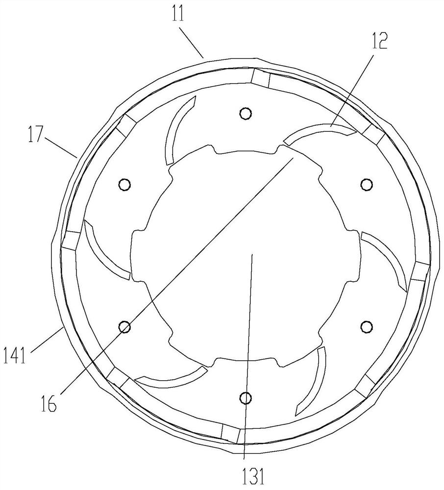
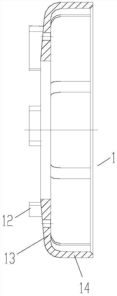
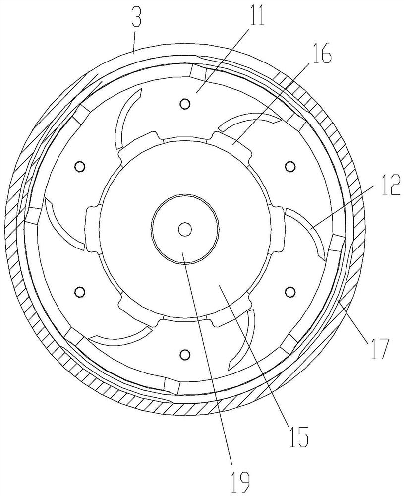
The invention provides a support structure and a compressor having the same. The support structure is used to be arranged under the motor of the compressor, and the support structure includes: a support ring, used for connecting with the casing of the compressor; a guide vane is provided on the end of the support ring close to the motor. The supporting structure of the present invention solves the problem of high exhaust oil discharge rate of the compressor in the prior art.

Description

technical field [0001] The present invention relates to the field of compressors, and in particular, to a support structure and a compressor having the same. Background technique [0002] At present, commercial multi-line compressors are widely used in various occasions, and the output of scroll compressors has also increased year by year. The scroll compressor is basically installed on the pump body, and the bottom of the motor is the lower support structure. Generally, the oil and gas mixture after the compressor will be collected into the upper cavity of the motor, while the lubricating oil generally flows back through the oil return pipe or the lower cavity of the motor through the trimming of the motor. The main balance block in the upper chamber of the motor has a greater stirring effect, and the fluid below will be sucked into the upper chamber of the motor through the through-flow hole or the gap between the stator and rotor. Affects the overall efficiency of the ai...

Claims


Application Information

Patent Timeline
Patent Type & Authority Patents(China)
IPC IPC(8): F04C18/02F04C29/02
CPCF04C18/0215F04C29/02F04C29/028
Inventor 陈可李伟余风利廖熠文翔欧阳沛文
Owner GREE ELECTRIC APPLIANCES INC
Learn More