Unlock instant, AI-driven research and patent intelligence for your innovation.
Reducer and washing machine using the reducer
What is Al technical title?
Al technical title is built by PatSnap Al team. It summarizes the technical point description of the patent document.
A washing machine and speed reducer technology, which is applied in the field of washing machines and can solve problems such as the speed difference between the pulsator and the agitator
Active Publication Date: 2022-03-15
QINGDAO HAIER WASHING MASCH CO LTD +1
View PDF6 Cites 0 Cited by
Summary
Abstract
Description
Claims
Application Information
AI Technical Summary
This helps you quickly interpret patents by identifying the three key elements:
Problems solved by technology
Method used
Benefits of technology
Problems solved by technology
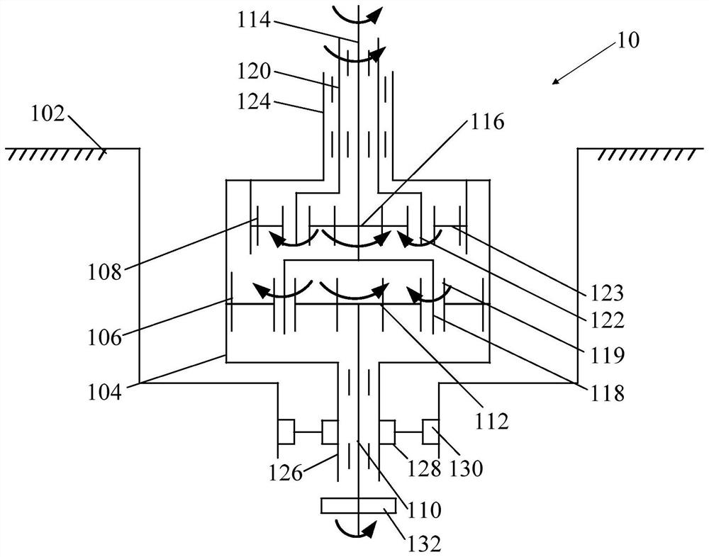
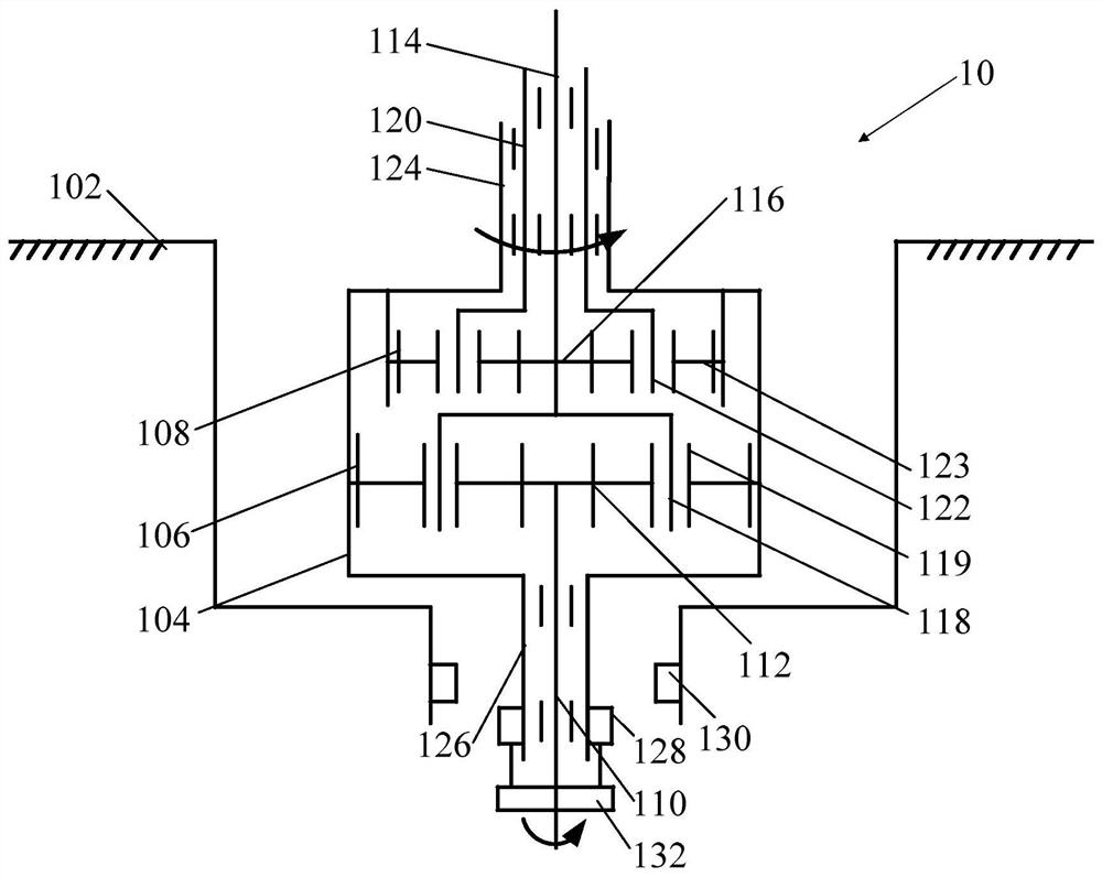
[0005] In order to solve the above-mentioned problems in the prior art, that is, in order to solve the problem that the pulsator and the agitator of the pulsator washing machine cannot form a speed difference when rotating, the first aspect of the present invention provides a speed reducer, the speed reducer The device includes a housing, a gear train, an input shaft, a first output shaft, and a second output shaft; the gear train is disposed in the housing; the input shaft is disposed on one side of the housing, and is connected to the One end of the gear train is connected; the first output shaft and the second output shaft are arranged on the other side of the housing and are respectively connected to the other end of the gear train, and the second output The shaft is sleeved on the first output shaft; the input shaft can drive the first output shaft and the second output shaft to rotate in the same direction through the gear train
Method used
Image
Click on the blue label to locate the original text in one second.
Reading with bidirectional positioning of images and text.
[0027] 在本发明的描述中,术语“第一”、“第二”、“第三”仅用于描述目的,而不能理解为指示或暗示相对重要性。 还需要说明的是,术语“设置”、“连接”应做广义理解,例如,可以是固定连接,也可以是可拆卸连接,或一体式连接;可以是直接相连,也可以通过中间媒介间接相连。 Those skilled in the art can understand the specific meanings of the above terms in the present invention according to specific situations.
[0028] figure 1 是本发明的减速器10的构造原理示意图。
[0029] Such as figure 1As shown, the speed reducer 10 of the present invention mainly includes a housing 102 , a gear train (not shown in the figure), an input shaft 110 , a first output shaft 114 and a second output shaft 120 . Wherein, the gear train is arranged in the housing 102 , and the...
PUM
Abstract
The invention relates to the technical field of home appliances, in particular to a speed reducer and a washing machine using the speed reducer. The present invention aims to solve the problem in the prior art that the pulsator and the agitator of the pulsator washing machine cannot form a difference in rotational speed when rotating. The present invention provides a speed reducer, which comprises a casing, a gear train, an input shaft, a first output shaft and a second output shaft; the gear train is arranged in the casing; the input shaft is arranged on one side of the casing, and Connected with one end of the gear train; the first output shaft and the second output shaft are arranged on the other side of the housing, and are respectively connected with the other end of the gear train, and the second output shaft is sleeved on the first output shaft ; The input shaft can drive the first output shaft and the second output shaft to rotate in the same direction through the gear train. The first output shaft is connected to the pulsator, and the second output shaft is connected to the agitator. Therefore, through the reducer of the present invention, the pulsator and the agitator can rotate in the same direction according to a preset speed ratio.
Description
technical field [0001] 本发明涉及家电技术领域,具体涉及一种减速器和采用该减速器的洗衣机。 Background technique [0002] 传统波轮洗衣机在洗涤状态时,由波轮带动波轮洗衣机内的衣物和水作定向转动,在衣物和水定向转动过程中实现洗涤衣物的目的。相对地,传统波轮洗衣机在脱水状态时,由内桶带动波轮洗衣机内的衣物作定向转动,在衣物的旋转过程中达到甩干的目的。传统波轮洗衣机的工作模式虽然能够基本满足洗涤衣物和甩干衣物的目的,但是,随着用户对波轮洗衣机的要求越来越高,传统波轮洗衣机在洗涤衣物和甩干衣物过程中的不足也随之暴露,例如,波轮洗衣机在洗涤衣物时波轮作定向转动,波轮带动衣物作单方向的定向转动,达不到“揉搓”衣物的效果,并且一直作单向转动的衣物容易缠绕在一起,洗涤效果很不好。 [0003] 为了解决上述问题,技术人员往往通过改进波轮与内桶的工作模式来解决衣物作单向转动的问题,即,在波轮洗衣机洗涤衣物时,驱动电机的驱动力通过波轮洗衣机的减速器分别传递至波轮和内桶,使波轮与内桶朝相反的方向转动,以此达到“揉搓”衣物的效果,以及减少衣物之间的相互缠绕。此结构的波轮洗衣机虽然基本解决了传统波轮洗衣机存在的问题,但是,在洗涤衣物过程中其仍存在一些问题,例如,水流单一,洗涤效果不好;内桶的工作频率和强度加大会导致减速器的故障率增加,而减速器维修工作难度大且维修成本高,导致用户的使用体验较变差。 [0004] 进一步地,为了降低波轮洗衣机减速器的故障率,以及增加波轮洗衣机的洗涤效果,本领域技术人员在波轮洗衣机内设置了搅拌器。该搅拌器与洗衣机的波轮同轴固定,并以相同的转速同向转动,从而增加洗衣机内的搅拌水流,提高波轮洗衣机的洗涤效果。但是,由于搅拌器和波轮只能以相同的转速同步转动,不能形成对衣物洗涤较为有利的紊乱的多重水流,所以本领域需要一种使搅拌器和波轮以不同转速转动的装置。 Contents of the invention [0005] 为了解决现有技术中的上述问题,即为了解决波轮洗衣机的波轮和搅拌器在转动时不能够形成转速差的问题,本发明的第一方面,提供了一种减速器,所述减速器包括壳体、齿轮系、输入轴、第一输出轴和第二输出轴;所述齿轮系设置在所述壳体内;所述输入轴设置在所述壳体的一侧,并且与所述齿...
Claims
Application Information
Patent Timeline
Application Date:The date an application was filed.
Publication Date:The date a patent or application was officially published.
First Publication Date:The earliest publication date of a patent with the same application number.
Issue Date:Publication date of the patent grant document.
PCT Entry Date:The Entry date of PCT National Phase.
Estimated Expiry Date:The statutory expiry date of a patent right according to the Patent Law, and it is the longest term of protection that the patent right can achieve without the termination of the patent right due to other reasons(Term extension factor has been taken into account ).
Invalid Date:Actual expiry date is based on effective date or publication date of legal transaction data of invalid patent.

