Hollow tube flange composite beam provided with internal and external stiffening ribs

A technology of composite beams and flanges, applied in bridges, buildings, etc., can solve problems such as difficult compaction of filled concrete, difficult construction, complex connection structure of filled concrete pipe flanges, etc., to achieve superior heat insulation and fire protection capabilities, and improve Cross-section utilization and material saving effects

Active Publication Date: 2017-11-24
CHANGAN UNIV
View PDF14 Cites 0 Cited by
  • Summary
  • Abstract
  • Description
  • Claims
  • Application Information

AI Technical Summary

Problems solved by technology

[0002] Steel-concrete composite structure bridges are generally formed by connecting the upper and lower flanges through the web to form an I-shaped beam structure. In order to enhance the strength and stability of the structure, stiffeners are welded on the web and the upper and lower flanges are connected The structure of the flange is appropriately improved, and the steel plate on the upper flange of the I-beam is replaced by the inner-filled concrete pipe flange. However, the inventor found the following problems in the construction of the inner-filled concrete pipe flange during further research and development: the inner-filled concrete pouring It is not easy to be compacted; the connection structure of the inner concrete pipe flange is complex and difficult to construct; new structures and new processes need to be proposed to ensure the mechanical performance at the connection position
[0003] At present, there are relatively few reports on this in the literature at home and abroad, and there are no effective technical measures for improvement.

Method used


Image

  • Hollow tube flange composite beam provided with internal and external stiffening ribs
  • Hollow tube flange composite beam provided with internal and external stiffening ribs
  • Hollow tube flange composite beam provided with internal and external stiffening ribs

Examples


Embodiment 1

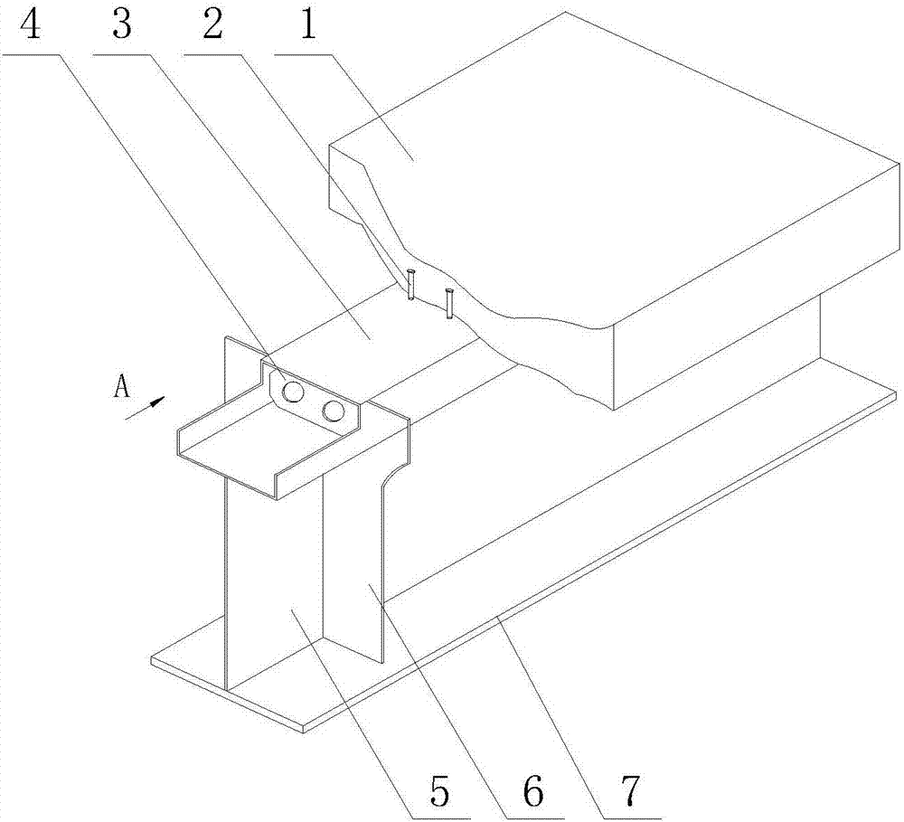
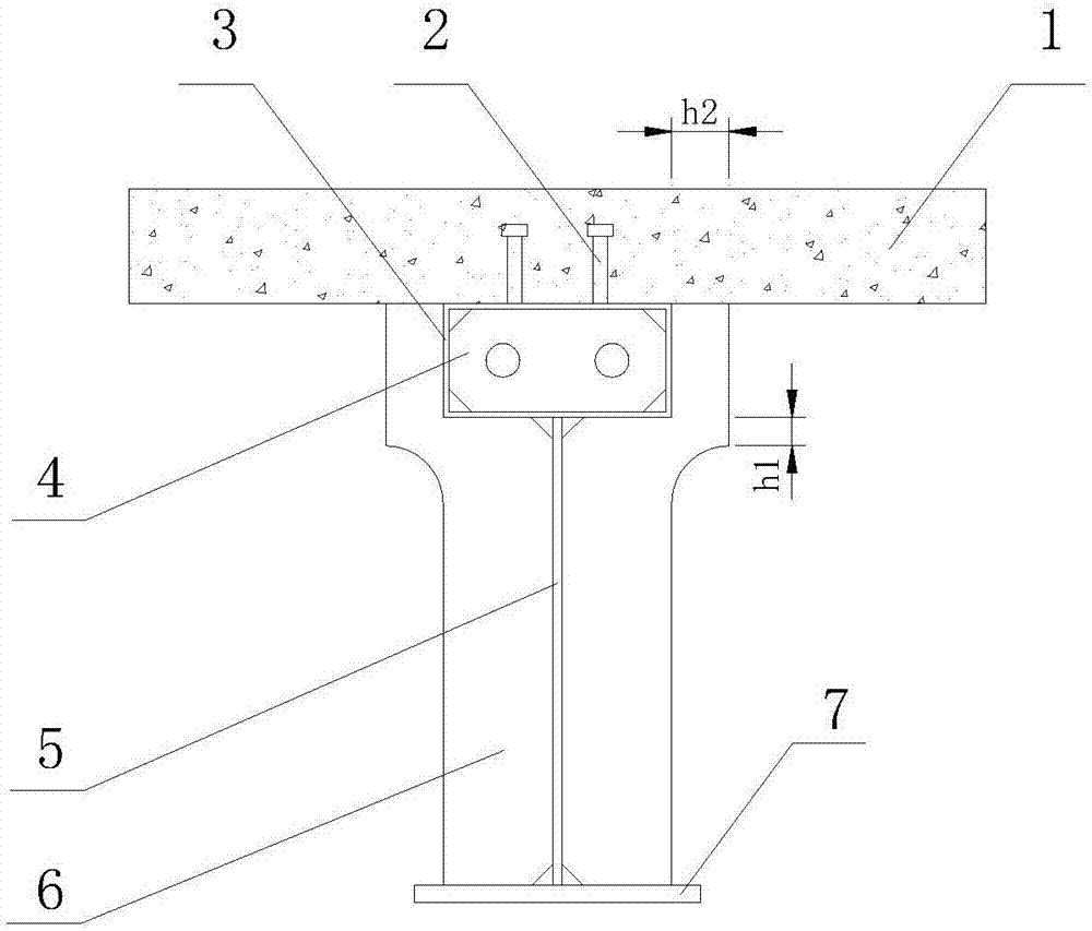
[0031] See figure 1 with figure 2 The inner-external stiffened hollow tube flange composite beam of this embodiment is composed of the top plate 1, the shear connector 2, the upper flange 3, the inner stiffener 4, the web 5, the outer stiffener 6 and the lower flange 7. constitute.

[0032] The lower flange 7 of this embodiment is a flange steel plate for ordinary steel bridges, that is, a rectangular steel plate with a length×width×height of 4300×200×12mm. The web 5 is welded to the middle of the lower flange 7. The lower flange 7 is vertical, the height of the web 5 is 328 mm, the thickness is 4 mm, and the length is equal to the length of the lower flange 7. An upper flange 3 is welded on the top of the web 5. The upper flange 3 of this embodiment is a rectangular hollow tubular structure, and is arranged parallel to the lower flange 7. Its length×width×height is 4300×160×80mm, and the wall thickness 4mm, two parallel shear connectors 2 are welded on the top of the upper fla...

Embodiment 2

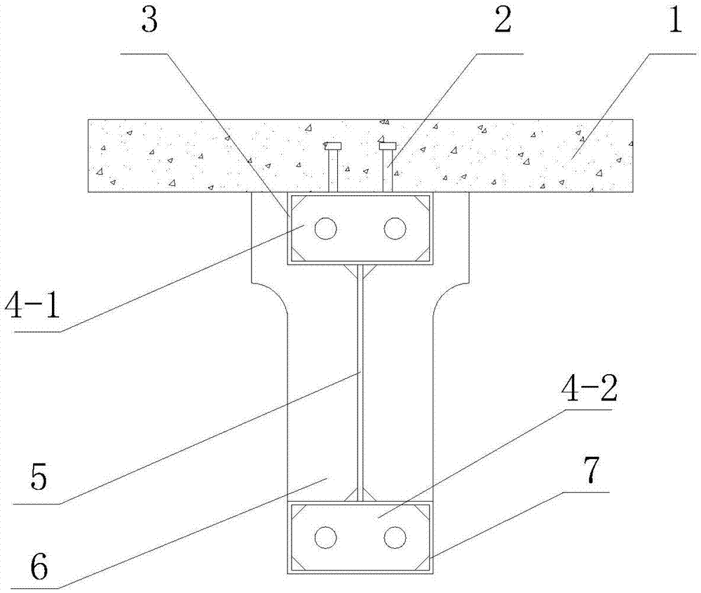
[0034] The upper flange 3 of this embodiment is a rectangular hollow tube structure, which is arranged in parallel with the lower flange 7. Its length×width×height is 1800×200×80mm, and the wall thickness is 4mm. Stiffener 4, the four top corners of the inner stiffener 4 are all processed into a chamfered structure, the chamfer is an isosceles triangle, the waist length is 1 / 5 of the side length of the upper flange 3, and the belly is welded in the middle of the lower flange 7. Plate 5, the height of the web 5 is 328mm, the thickness is 4mm, and the length is equal to the length of the lower flange 7. On the left and right sides of the web 5, there are welded vertical external stiffeners 6, and the upper section of the external stiffener 6 is connected with The lower sections are connected by arc sections, and the lateral width of the upper section is smaller than the width of the lower section, and the longitudinal distance between the highest point of the arc section and the l...

Embodiment 3

[0037] The upper flange 3 of this embodiment is a rectangular tubular structure, which is arranged in parallel with the lower flange 7. Its length×width×height is 60000×700×200mm, and the wall thickness is 18mm. The inner cavity of the upper flange 3 is welded with internal stiffeners. The four top corners of rib 4 and inner stiffener 4 are all processed into a chamfer structure, the chamfer is an isosceles triangle, the waist length is 9 / 40 of the side length of the upper flange 3, and the web is welded in the middle of the lower flange 7. 5. The height of the web 5 is 2500mm, the thickness is 20mm, and the length is equal to the length of the lower flange 7. On the left and right sides of the web 5, there are welded vertical external stiffeners 6, and the upper and lower sections of the external stiffeners 6 Are connected by arc segments, and the lateral width of the upper segment is smaller than the width of the lower segment, the longitudinal distance between the highest poi...


PUM


Abstract

The invention relates to a hollow tube flange composite beam provided with internal and external stiffening ribs. A web is provided between an upper flange and a lower flange, an I-shaped beam is thus formed, the external stiffening ribs are arranged on the web perpendicularly, a top plate is arranged on the top of the upper flange, the upper flange is arranged as a hollow tube or both the upper flange and the lower flange are arranged as hollow tubes, the internal stiffening ribs are arranged in the hollow tubes or the hollow tubes are filled with a foaming steel material, the internal stiffening ribs and the external stiffening ribs are positioned on the same cross section, and the upper flange and the top plate are connected by shear connectors. The local buckling problem of the upper flange can be effectively controlled by the internal and external stiffening ribs, the construction process is simplified, security and stability at the stages of structure construction and use are guaranteed, the advantages of materials of the steel-concrete composite structure are given full play, the construction period is short, the dead-weight of the structure is small, the building height is small, the material properties of steel and concrete can be fully embodied, and the hollow tube flange composite beam provided with the internal and external stiffening ribs has better application prospects when compared with traditional I-shaped composite beams.

Description

Technical field [0001] The invention belongs to the technical field of steel-concrete composite structure bridges, and particularly relates to an internal-external stiffened hollow pipe flange composite beam. Background technique [0002] Steel-concrete composite structure bridges are generally connected by the upper flange and lower flange through the web to form an I-beam structure. In order to enhance the strength and stability of the structure, the web is welded with stiffeners and the upper flange, lower flange The flange structure is appropriately improved, and the upper flange steel plate of the I-beam is replaced with the inner concrete pipe flange. However, the inventor found that the inner concrete pipe flange has the following problems in the construction during the further research and development process: It is not easy to compact; the connection structure of the flange of the filled concrete pipe is complicated and the construction is difficult; new structures and n...

Claims


Application Information

Patent Timeline
Patent Type & Authority Applications(China)
IPC IPC(8): E01D2/02
CPCE01D2/02
Inventor 王春生段兰王茜张文婷王晓平刘浩李熙同崔冰朱经纬崔志强
Owner CHANGAN UNIV
Why Eureka
Try Eureka