
Wireless-controlled lock control method

A control method and wireless control technology, applied in the field of locks, can solve the problems of high cost, high power consumption, and expensive bicycle locks, and achieve the effects of high reliability, low cost, and low power consumption

Inactive Publication Date: 2017-11-24
DYNAMICODE
View PDF9 Cites 1 Cited by
  • Summary
  • Abstract
  • Description
  • Claims
  • Application Information

AI Technical Summary

Benefits of technology

This technology described for controlling wireless controlled latches used in horseback traps allows them to have lower costs while still being reliable over long periods of use without requiring constant maintenance or recharged batteries. It also enables remote access from mobile devices like smartphones through radio waves instead of wired connections.

Problems solved by technology

Invention describes a problem where traditional keys are hard to transport due to their bulky size and lacking convenience during rental cycles. There also exist concerns over losing them because they cannot easily turn off these locked devices remotely without being able to access them again after usage. Therefore, researchers aimed at developing better solutions involving electronic controls instead of physical ones such as motors.

Method used


Image

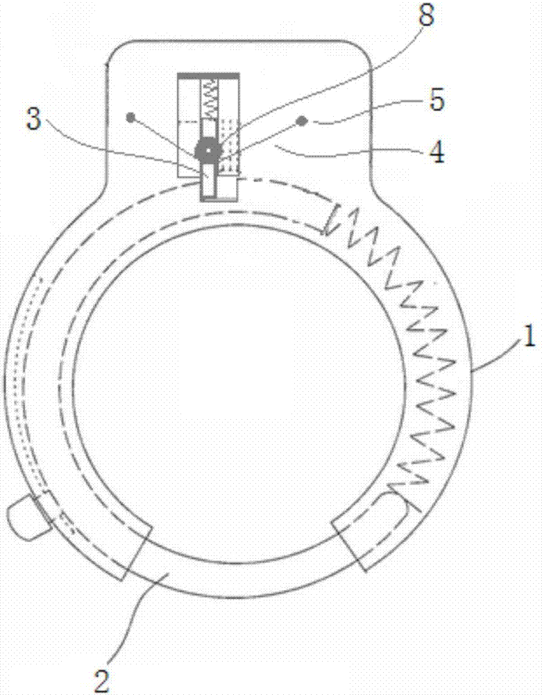
  • Wireless-controlled lock control method
  • Wireless-controlled lock control method
  • Wireless-controlled lock control method

Examples


Embodiment Construction

[0022] In order to make the technical means, creative features, goals and effects achieved by the present invention easy to understand, the present invention will be further described below in conjunction with specific illustrations.

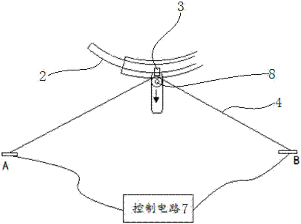
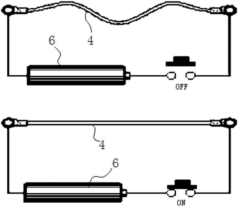
[0023] This solution is based on wireless signal transmission technology, and receives instructions from external control components (such as smart phones, PADs, or other controllers) to control the power-on state of the nickel-titanium alloy wire set in the lock; the nickel-titanium alloy wire changes according to the power-on state Deformation is generated to drive the lock to lock or / and unlock.

[0024] On this basis, in the whole control process of this scheme, the electrification state of the nickel-titanium alloy wire set in the lock can be further adjusted according to the temperature of the nickel-titanium alloy wire, so that the nickel-titanium alloy wire can be adjusted according to the dynamically adjusted electrification state. Chan...


PUM

PropertyMeasurementUnit
Phase transition temperatureaaaaaaaaaa
Tensile strengthaaaaaaaaaa
Yield strengthaaaaaaaaaa

Abstract

The invention discloses a wireless-controlled lock control method which comprises the following steps that a wireless-controlled lock receives a command of an external control part, and/or an electrifying state of a nickel-titanium alloy wire arranged in the lock is controlled according to the temperature of the nickel-titanium alloy wire; and the nickel-titanium alloy wire deforms according to a change of the electrifying state to drive the lock to be locked and/or unlocked. The wireless-controlled lock control method provided by the technical scheme has the characteristics of low cost, low power consumption and high reliability and effectively solves the problems in the prior art.

Description


Claims


Application Information

Patent Timeline
Owner DYNAMICODE
Learn More