Touch substrate, touch panel, display substrate, display panel and display device

A technology for display substrates and substrates, which is applied in the fields of display substrates, touch panels, display panels and display devices, and touch substrates, and can solve the problem of not increasing the production cost of display screens and touch screens, and disadvantageously narrow frame areas. Problems such as borders, to achieve the effect of reducing the border, reducing the border area, reducing the border width and border area

Active Publication Date: 2021-01-29
BOE TECH GRP CO LTD
View PDF7 Cites 0 Cited by
  • Summary
  • Abstract
  • Description
  • Claims
  • Application Information

AI Technical Summary

Problems solved by technology

[0003] like figure 1 As shown, the current touch screen and the wiring 6 in the frame area 5 of the display screen occupy a relatively large area, resulting in a wide width of the frame area 5, which is not conducive to realizing a narrow frame
In addition, the current touch screens and displays do not have an efficient design that can achieve narrow borders due to technological capabilities and manufacturing cost requirements.
[0004] Therefore, how to realize the narrow frame of the display screen and touch screen without increasing the existing process capability and production cost has become a technical problem to be solved urgently.

Method used


Image

  • Touch substrate, touch panel, display substrate, display panel and display device
  • Touch substrate, touch panel, display substrate, display panel and display device
  • Touch substrate, touch panel, display substrate, display panel and display device

Examples


Embodiment 1

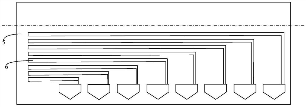
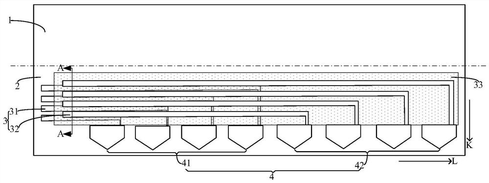
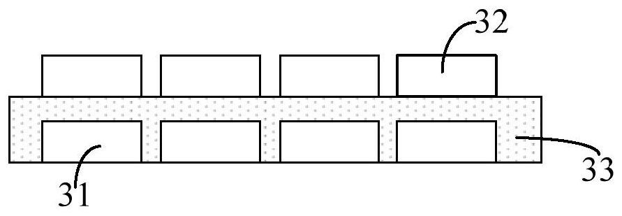
[0031] This embodiment provides a touch substrate, such as figure 2 As shown, including the touch area 1 and the frame wiring area 2, the plane parallel to the touch substrate is used as the projection plane, and the electrode lines 3 of the frame wiring area 2 are distributed on different layers, and are distributed on different layers. The orthographic projections of the electrode lines 3 and the areas between the electrode lines 3 on the projection plane overlap.

[0032] It should be noted that, in this embodiment, the orthographic projection of the electrode lines 3 distributed on each layer and the area between the electrode lines 3 on the projection plane is a whole area, as long as the electrode lines distributed on different layers 3 and the overall area corresponding to the area between the electrode lines 3 overlap, which can reduce the layout width of the electrode lines 3 in the frame wiring area 2 . figure 2 Shown in is the situation that the orthographic proj...

Embodiment 2

[0041] This embodiment provides a touch substrate, which is different from that in Embodiment 1, such as Figure 5 As shown, in the wiring area 2 of the frame, the electrodes 4 connected to the electrode lines 3 are located on the layer where the electrode lines 3 are located, and the electrodes 4 of different layers are arranged to form different straight lines, and the orthographic projections of the straight lines on the projection plane are parallel to each other.

[0042] in, Figure 5 What is shown in is the case where the orthographic projections of the area between the electrode lines 3 distributed on each layer overlap on the projection plane, and this situation also belongs to the electrode lines distributed on different layers protected by the present invention 3 and the orthographic projections of the area between the electrode lines 3 on the projection plane overlap.

[0043] Correspondingly, in this embodiment, in the wiring area 2 of the frame, the electrode 41...

Embodiment 3

[0048] This embodiment provides a touch panel, including the touch substrate in any one of Embodiments 1-2.

[0049] By using the touch substrate in Embodiment 1 or 2, the frame of the touch panel can be reduced, so that the touch panel can achieve a narrow frame.


PUM


Abstract

The invention provides a touch substrate, a touch panel, a display substrate, a display panel and a display device. The touch substrate includes a touch area and a frame wiring area. The plane parallel to the touch substrate is used as a projection plane. The electrode lines in the frame wiring area are distributed on different layers, and the electrode lines distributed on different layers There is overlap in the orthographic projection of the area between the electrode lines and the electrode lines on the projection plane. The touch substrate distributes the electrode lines in the wiring area of ​​the frame on different layers, and the orthographic projections of the electrode lines distributed on different layers and the areas between the electrode lines on the projection plane overlap. In the prior art, the electrode lines in the frame wiring area are all distributed on the same layer, which greatly reduces the layout width of the electrode lines in the frame wiring area, thereby greatly reducing the electrode lines in the frame wiring area. The occupied frame width and frame area realize the narrow frame of the touch substrate.

Description

technical field [0001] The present invention relates to the field of display technology, in particular to a touch substrate, a touch panel, a display substrate, a display panel and a display device. Background technique [0002] At present, display products are increasingly pursuing lightness and high quality, and narrow bezel design has always been a technology to improve product quality. In the current touch display screen, both the display screen and the touch screen need to be designed with a narrow frame, so as to realize the narrow frame of the overall touch display screen. [0003] Such as figure 1 As shown, the wiring 6 of the current touch screen and display screen frame area 5 occupies a relatively large area, resulting in a wide width of the frame area 5, which is not conducive to realizing a narrow frame. In addition, the current touch screens and display screens do not have an efficient design that can achieve narrow borders due to technological capabilities a...

Claims


Application Information

Patent Timeline
Patent Type & Authority Patents(China)
IPC IPC(8): G06F3/041G02F1/1333
CPCG02F1/13338G06F3/041G06F2203/04103G06F3/0412G06F3/04164H10K59/40H10K59/131G09G2300/0426G02F1/13452G02F1/13629
Inventor 王明玺
Owner BOE TECH GRP CO LTD
Why Eureka
Try Eureka