Electro-luminescence display apparatus

一种电致发光显示、设备的技术,应用在电路、电气元件、静态指示器等方向,能够解决不均匀亮度等问题,达到窄边框、提高亮度均匀性的效果

Active Publication Date: 2018-05-11
LG DISPLAY CO LTD
View PDF4 Cites 18 Cited by
  • Summary
  • Abstract
  • Description
  • Claims
  • Application Information

AI Technical Summary

Problems solved by technology

Therefore, if the distance from the cathode voltage supply unit capable of supplying the cathode voltage ELVSS to the common electrode increases, a problem of uneven brightness occurs

Method used


Image

  • Electro-luminescence display apparatus
  • Electro-luminescence display apparatus
  • Electro-luminescence display apparatus

Examples


Embodiment approach

[0279] According to still another exemplary embodiment of the present disclosure, the capacitor electrode 1125 may be made of the semiconductor layer 416 having conductive properties, and as Figure 11 Connected to gate 420 as shown. But the present disclosure is not limited thereto, and the capacitor electrode 1125 may be configured as the capacitor electrode 425 of another exemplary embodiment of the present disclosure.

[0280] According to the above configuration, the light-shielding capacitor electrode 1126 can generate double capacitance. Accordingly, capacitance can be increased in a relatively small area. As a result, it is beneficial to realize a high-resolution top emission type electroluminescent display device and if the stacked structure and thickness of the light-shielding capacitor electrode 1126 and the source electrode 424 are the same as those of the light-shielding capacitor electrode 1126, and the source electrode 424 can be manufactured by the same manufa...


PUM

PropertyMeasurementUnit
absorptanceaaaaaaaaaa

Abstract

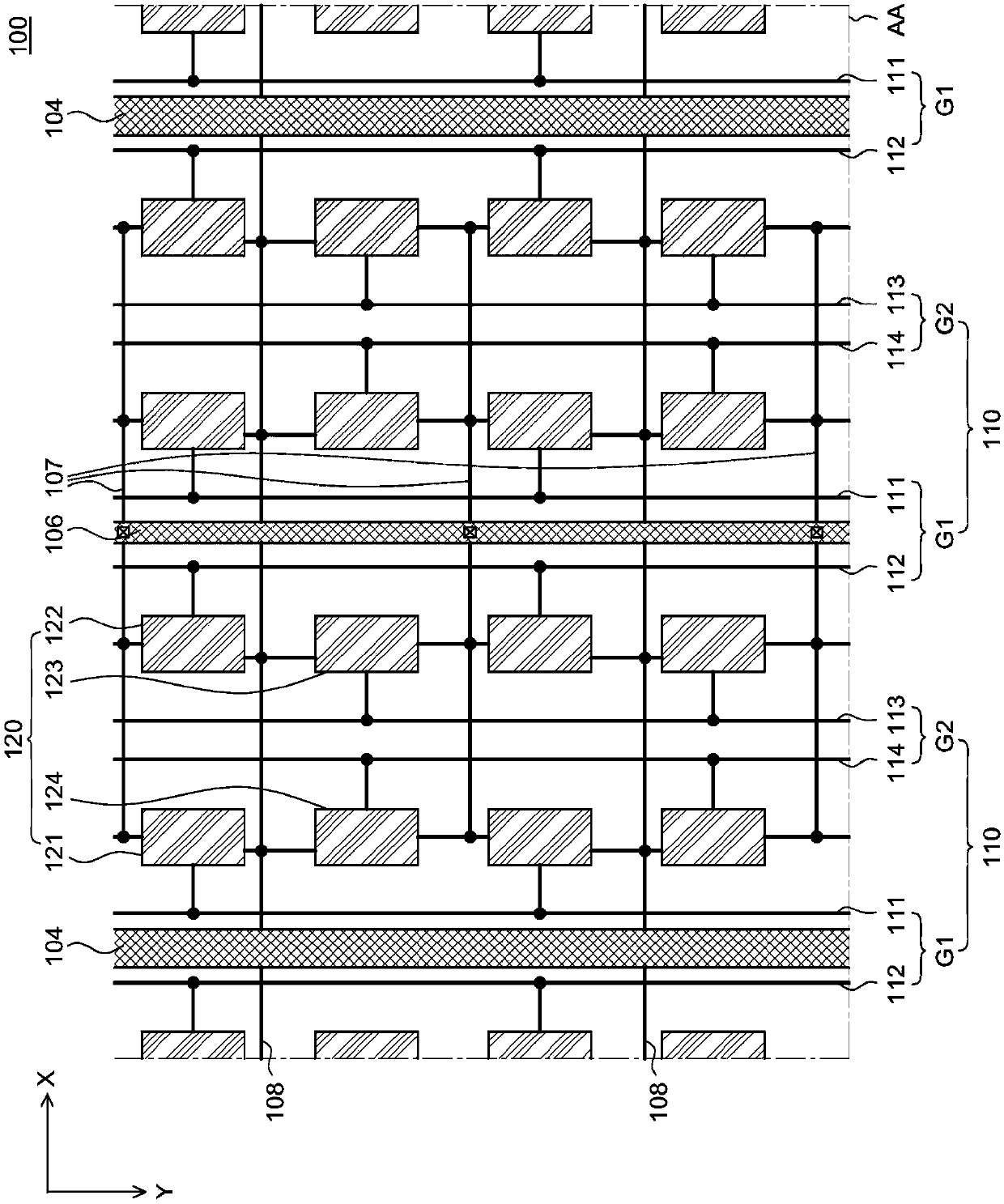
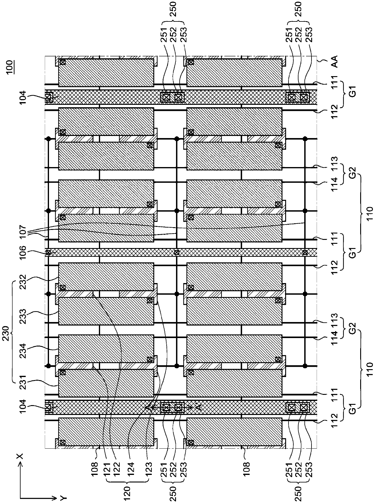
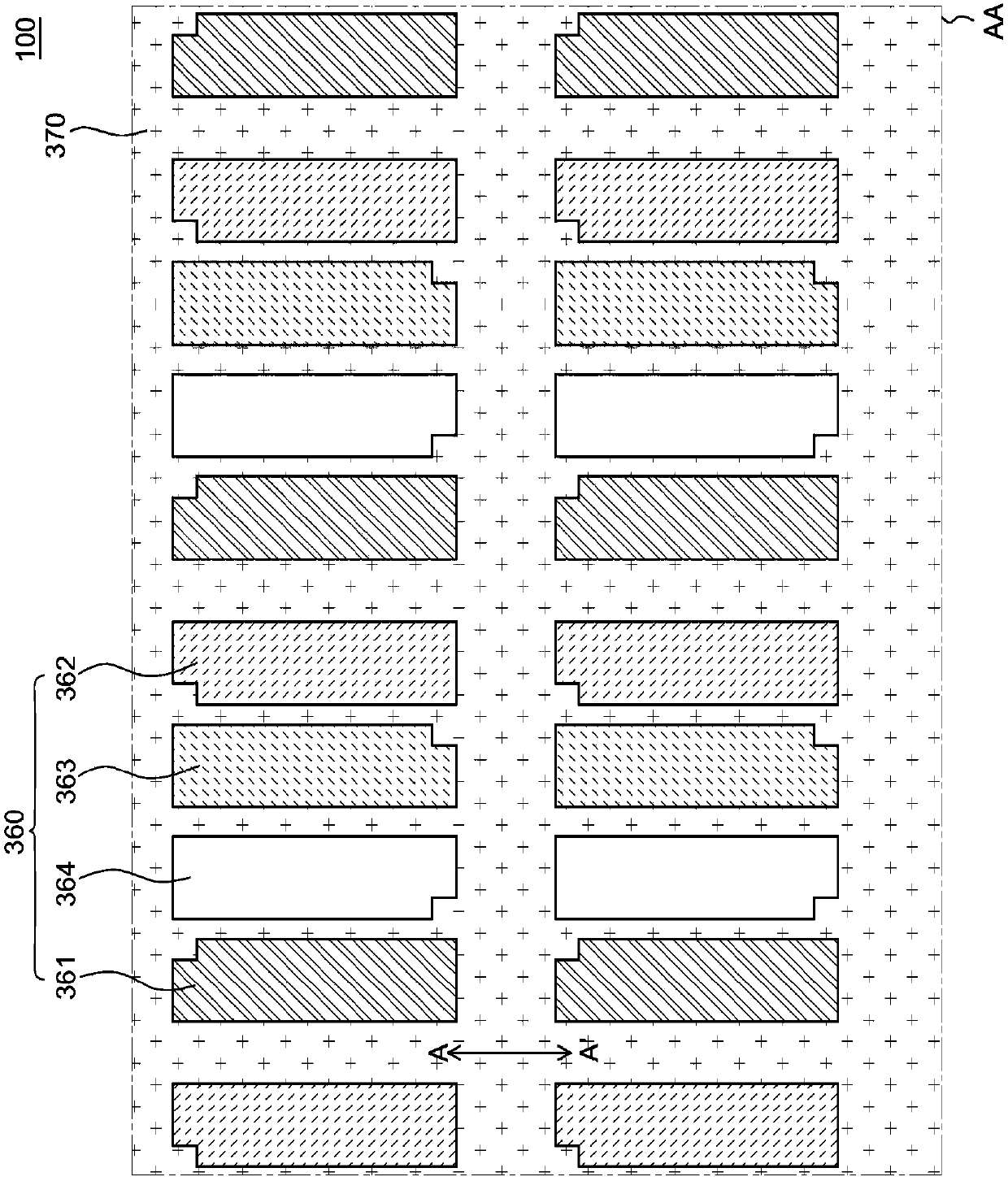
An electroluminescence display apparatus comprising: a plurality of sub-pixel circuit units arranged in a matrix form; at least one gate line disposed between the plurality of sub-pixel circuit unitsand extending along a first direction; a plurality of first data line groups and a plurality of second data line groups alternatively disposed between the plurality of sub-pixels circuit units and extending along a second direction; a plurality of common lines disposed within the first or the second data line groups and extending along the second direction; and a plurality of anode lines disposedwithin the first or the second data line groups and extending along the second direction.

Description

technical field [0001] The present disclosure relates to a top emission type electroluminescence display device capable of improving electroluminescence by reducing the degree of deviation in potential between an anode and a cathode according to the position of each pixel within a pixel region of the electroluminescence display device Brightness uniformity of the display device. The electroluminescent display device of the present disclosure is also capable of improving the uniformity of potential when the electroluminescent display device is enlarged. Background technique [0002] An organic light-emitting display device, which is a self-luminous display device, does not require a separate or additional light source like a liquid crystal display device, and thus can be reduced in weight and thickness. In addition, the organic light emitting display device is advantageous not only in low power consumption due to its low driving voltage, but also in fast response speed, wide...

Claims


Application Information

Patent Timeline
Patent Type & Authority Applications(China)
IPC IPC(8): H01L27/32H01L51/56H01L51/52
CPCH10K59/123H10K59/1315H10K59/12H10K59/131H10K50/814H10K50/82G09G3/3225G09G2300/0426G09G2300/0452G09G2300/0465G09G2320/0223G09G2330/021H01L29/78633H01L27/124H01L27/1255G09G2320/0209H10K59/351H10K59/122H10K50/865H10K59/38H10K59/1216H10K50/844H10K59/124H10K59/126H10K2102/3026H01L27/1248
Inventor 金正默
Owner LG DISPLAY CO LTD
Why Eureka
Try Eureka