Method applied to wireless communication UE and wireless communication base station, and device

A wireless communication and wireless signal technology, applied in wireless communication, signaling distribution, sustainable communication technology, etc., can solve problems such as low transmission delay

Active Publication Date: 2017-11-28
SHANGHAI LANGBO COMM TECH CO LTD
View PDF3 Cites 19 Cited by
  • Summary
  • Abstract
  • Description
  • Claims
  • Application Information

AI Technical Summary

Problems solved by technology

In some special scenarios, IoT communication requires low transmission delay, bu

Method used


Image

  • Method applied to wireless communication UE and wireless communication base station, and device
  • Method applied to wireless communication UE and wireless communication base station, and device
  • Method applied to wireless communication UE and wireless communication base station, and device

Examples


Example Embodiment

[0165] Example 1

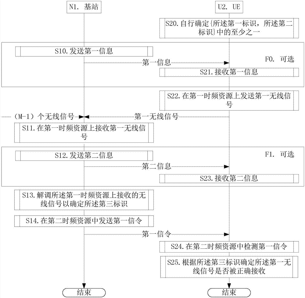
[0166] Embodiment 1 illustrates the flow chart of uplink transmission, as attached figure 1 Shown. Attached figure 1 , The base station N1 is the maintenance base station of the serving cell of the UE U2, and the steps identified in the block F0 and the block F1 are optional.

[0167] for Base station N1 , Send the first information in step S10, receive the first wireless signal on the first time-frequency resource in step S11, send the second information in step S12, and demodulate the first wireless signal on the first time-frequency resource in step S13 The received wireless signal determines the third identifier, and the first signaling is sent in the second time-frequency resource in step S14.

[0168] for UE U2 , Determine at least one of {the first identifier, the second identifier} in step S20, receive the first information in step S21, and send the first radio on the first time-frequency resource in step S22. Signal, receive the second information in s...

Example Embodiment

[0175] Example 2

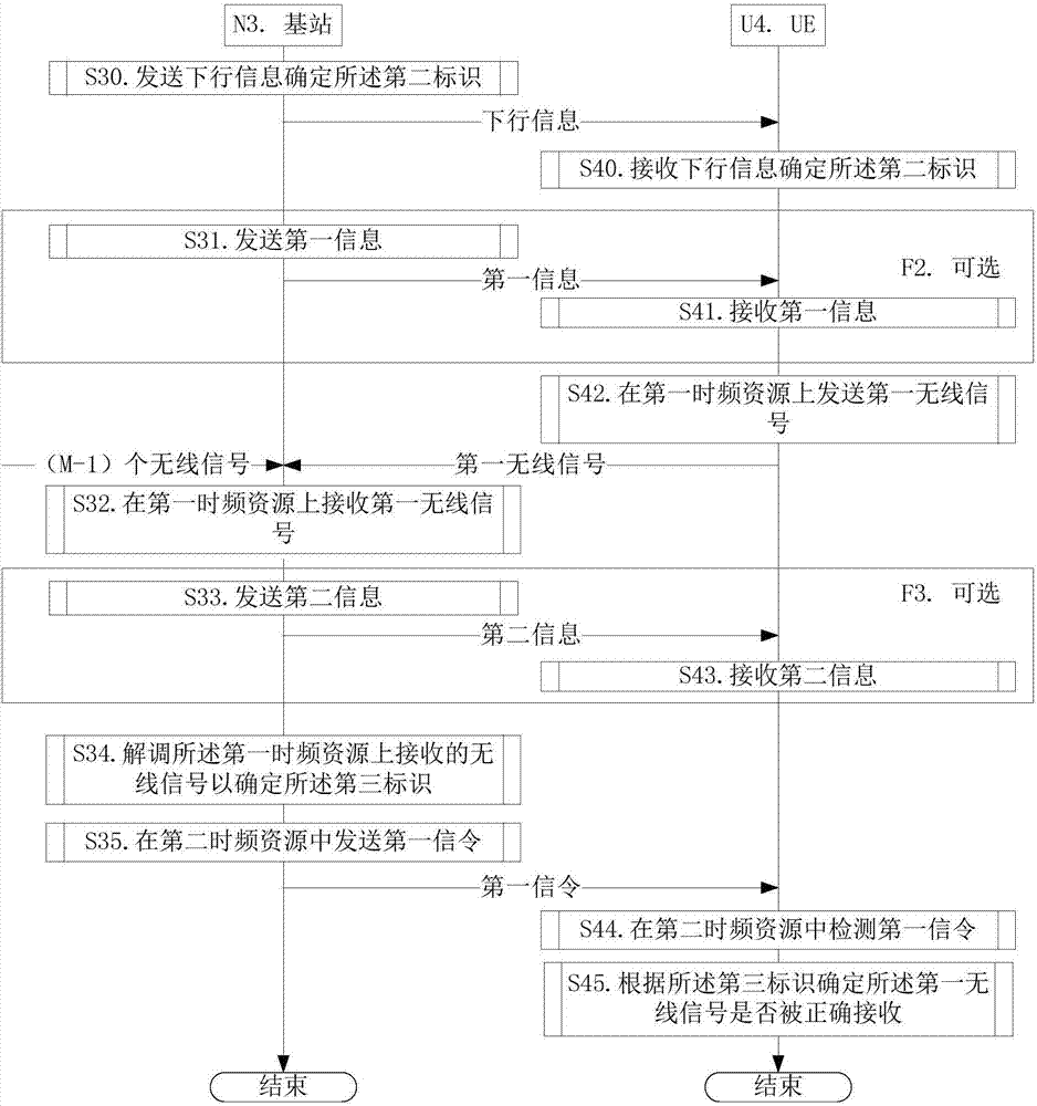
[0176] Embodiment 2 illustrates the flow chart of uplink transmission, as attached figure 2 Shown. Attached figure 2 Among them, base station N3 is the maintenance base station of the serving cell of UE U4, and the steps identified in block F2 and block F3 are optional.

[0177] for Base station N3 In step S30, downlink information is sent to determine the second identifier, in step S31, the first information is sent, in step S32, the first wireless signal is received on the first time-frequency resource, and the second information is sent in step S33. In step S34, the wireless signal received on the first time-frequency resource is demodulated to determine the third identifier, and in step S35, the first signaling is sent in the second time-frequency resource.

[0178] for UE U4 , Receiving downlink information in step S40 to determine the second identifier, receiving first information in step S41, sending the first wireless signal on the first time-frequency...

Example Embodiment

[0185] Example 3

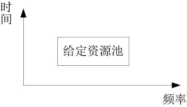
[0186] Embodiment 3 illustrates a schematic diagram of the given resource pool according to the present invention. Wherein, the given resource pool is one of {the first resource pool, the second resource pool}.

[0187] Such as image 3 As shown, the given resource pool is continuous in both the time domain and the frequency domain.

[0188] As a sub-embodiment, the given resource pool is the first resource pool.

[0189] As a sub-embodiment, the given resource pool is the second resource pool.


PUM


Abstract

The invention discloses a method applied to a wireless communication UE and a wireless communication base station, and a device. UE sends a first wireless signal in a first time-frequency resource and detects a first signal in a second time-frequency resource. The first time-frequency resource is automatically selected by the UE. A first parameter set comprises at least one of {a first identifier and a second identifier}. The first signal is used for determining a third identifier. The UE judges whether the first wireless signal is accurately received by the base station or not by comparing the third identifier with the second identifier. According to the method and the device, through design of the second identifier and the third identifier, the problem of how to know that the sent uplink data is accurately received, by the UE in scheduling-free uplink transmission is solved. Moreover, a relation is established between the first parameter set, and the first time-frequency resource and the second time-frequency resource, so the UE and the base station can obtain the uplink data and feedback corresponding to the uplink data on fixed resources, and the blind detection complexity is reduced.

Description

technical field [0001] The present invention relates to a wireless signal transmission scheme in a wireless communication system, in particular to a method and device for uplink transmission and downlink feedback based on cellular network communication. Background technique [0002] In a traditional wireless communication system based on digital modulation, such as a 3GPP (3rd Generation Partner Project, 3rd Generation Partnership Project) cellular system, uplink wireless signal transmission is based on base station scheduling. For the next generation wireless communication system, IoT (Internet of Things, Internet of Things) communication may become an important application scenario. [0003] The characteristics of IoT communication include: the number of terminal devices is very large, the standby time supported by terminal devices is long (low power consumption), and the cost of terminal devices is low. Traditional scheduling-based uplink transmissions are no longer suit...

Claims


Application Information

Patent Timeline
IPC IPC(8): H04L1/18H04L5/00H04W72/04H04W72/12
CPCH04L1/1812H04L1/1861H04L5/0053H04L5/0055H04W72/0446H04W72/0453H04W72/1268H04W72/21H04W72/04Y02D30/70
Inventor 张晓博蒋琦
Owner SHANGHAI LANGBO COMM TECH CO LTD
Why Eureka
Try Eureka