Production method and device of electric precipitator cathode lines

A technology of electrostatic precipitator and production equipment, applied in the direction of electrode structure, electrostatic separation, etc., can solve the problems of low production output, poor quality consistency, and low overall production efficiency, and achieve the effects of high production efficiency, reduced investment, and simple structure

Active Publication Date: 2017-12-01
郴州万墨环保科技有限公司
View PDF7 Cites 2 Cited by
  • Summary
  • Abstract
  • Description
  • Claims
  • Application Information

AI Technical Summary

Problems solved by technology

[0003] At present, on the one hand, our domestic environmental protection enterprises adopt the mode of manual production, and their production output and quality are heavily dependent on manual labor, with low production output and poor quality consistency.
[0004] On the other hand, the molten metal is poured into the mold, and then punched into a tooth shape by a punching machine. However, in the punching process, only one segment is punched, and continuous punching cannot be achieved. Therefore, the overall production efficiency is low and cannot be adapted to the cathode line. demand status

Method used


Image

  • Production method and device of electric precipitator cathode lines
  • Production method and device of electric precipitator cathode lines
  • Production method and device of electric precipitator cathode lines

Examples


Embodiment

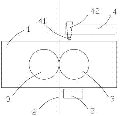
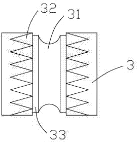
[0032] Such as Figure 1~2 As shown, a cathode wire production device for an electrostatic precipitator includes a production stand 1 and a steel core wire 2 vertically installed in the production stand. Two press rollers 3 are also arranged in the production stand 1, and the press roller 3 includes Cylindrical body, the cylindrical outer surface of the pressure roller 3 is provided with a groove 31 around the cylinder, along the two sides of the groove 31, there are tooth groove structures 32 connected with the groove, and the cylinders of the two pressure rollers 3 The outer surface of the shape is closely arranged and the positions of the two grooves 31 are aligned, the inner surfaces of the two grooves 31 are arranged symmetrically with respect to the steel core wire 2, and the positions of the tooth groove structures 32 of the two pressure rollers are corresponding.

[0033] The tooth portion of the tooth groove structure 32 may specifically be a zigzag tooth portion, a r...


PUM


Abstract

The invention relates to the technical field of dedusting cathode line production equipment, and discloses a production method and device of electric precipitator cathode lines. The production device comprises a production rack and a steel core line which is vertically arranged in the production rack. Two press rollers are arranged in the production rack. Each press roller comprises a cylindrical body, a groove is formed in the cylindrical outer surface of the press roller around the cylinder, and the two sides of the groove are provided with tooth groove structures communicating with the grooves. The cylindrical outer surfaces of the two press rollers are attached to each other, and the two grooves are located in the same plane. The inner surfaces of the two grooves are symmetrically arranged relative to the steel core line. The tooth groove structures of the two press rollers correspond in position. The grooves formed in the press rollers and the tooth groove structures arranged on the press rollers serve as forming molds of cathode bars and discharging racks of the cathode lines. A cooling device arranged at a discharging port of the grooves can make the cathode lines of an alloy solution be formed rapidly, that is, in the process that the alloy solution is fed into a feeding port, the formed cathode lines are continuously produced from the discharging port of the grooves, no middle process is additionally conducted, and the production efficiency is high.

Description

technical field [0001] The invention relates to the technical field of dust removal cathode wire production equipment, in particular to a production method and device for an electric dust collector cathode wire. Background technique [0002] As an essential part of the dust removal equipment in power plants, the cathode line of the electrostatic precipitator is used more and more in the context of more and more important and stricter environmental protection, and the corresponding production capacity demand is increasing . [0003] At present, on the one hand, our domestic environmental protection enterprises mainly adopt the mode of manual production, and their production output and quality are heavily dependent on manual labor, with low production output and poor quality consistency. [0004] On the other hand, the molten metal is poured into the mold, and then punched into a tooth shape by a punching machine. However, in the punching process, it can only be punched secti...

Claims


Application Information

Patent Timeline
Patent Type & Authority Applications(China)
IPC IPC(8): B22D18/02B22D25/04B03C3/41
CPCB03C3/41B22D18/02B22D25/04Y02A50/2351
Inventor 王振华
Owner 郴州万墨环保科技有限公司
Why Eureka
Try Eureka